As I age, most of the stuff that frightened throughout my life seem silly in retrospect. Two items are firmly cemented in that list though: the fear of losing the people I love and the fear of the USB specification.
In this blog post, we will investigate the USB Power Delivery (USB-PD) standard – the part of the spec that lets us pull up to 48 V and 5 A from a USB-C port. We will use this knowledge to build a trigger board, a device to harvest the USB-PD power and pipe it into our projects.
Come with me, and I promise that, by the end of this post, the USB specification will not out us as sure imposters to our friends. Instead, we will tame its power and remain ever secretly unsure of our skills.
USB Type-C Current
Before jumping into USB-PD, let’s take a look at some simpler ways to pull power from a USB port. In the days before USB-C, USB 2.0 simply stated that a compliant host port must provide 500 mA at 5 V. By USB 3.2, the current was bumped to 900 mA.
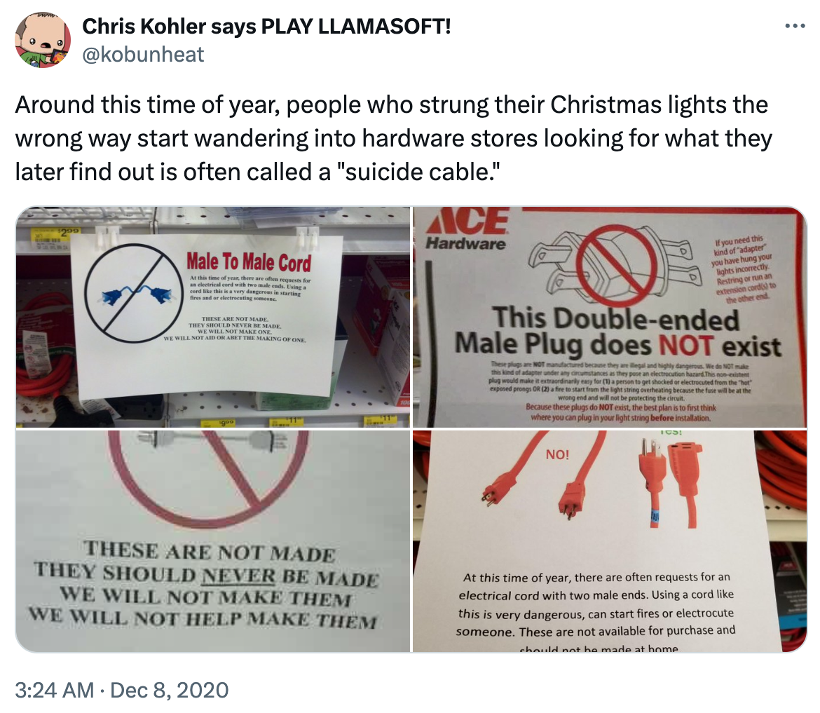
In this world, USB cables are asymmetrical – the plug at the power provider is different than the plug at power receiver. Think of how the two ends of those old USB printer cables look, or the two ends of a micro USB cable. The hardware makes it impossible to connect two ports providing power:
Then came USB-C with its hip symmetrical cable and reversible plug. We may now work with up to 3 A of current at 5 V! Except, now the plug hardware doesn’t prevent us from stringing two power sources together, and we need a mechanism to let both sides of the cable agree on who is providing (a source) and who is taking power (a sink).
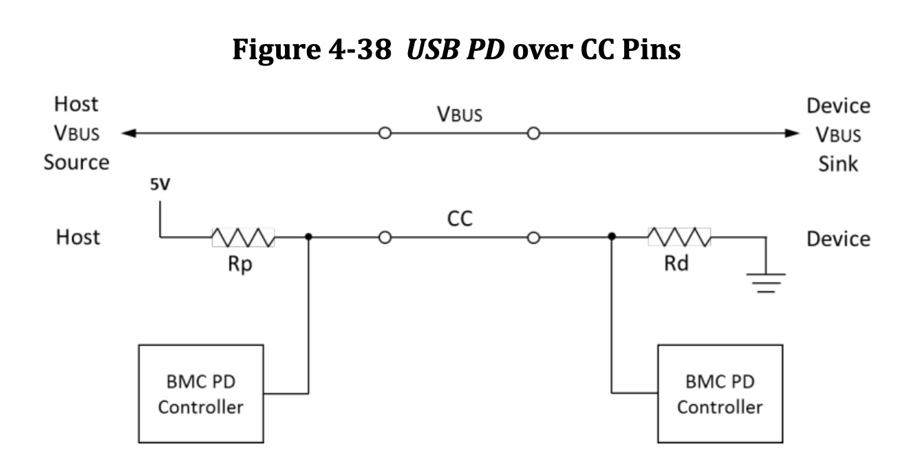
Out of the 24 pins in a USB-C connector, two are dedicated to this operation: CC1 and CC2, the Configuration Channels. The spec defines how sources and sinks monitor the voltage on these pins (section 4.6.2.1 of [1]):
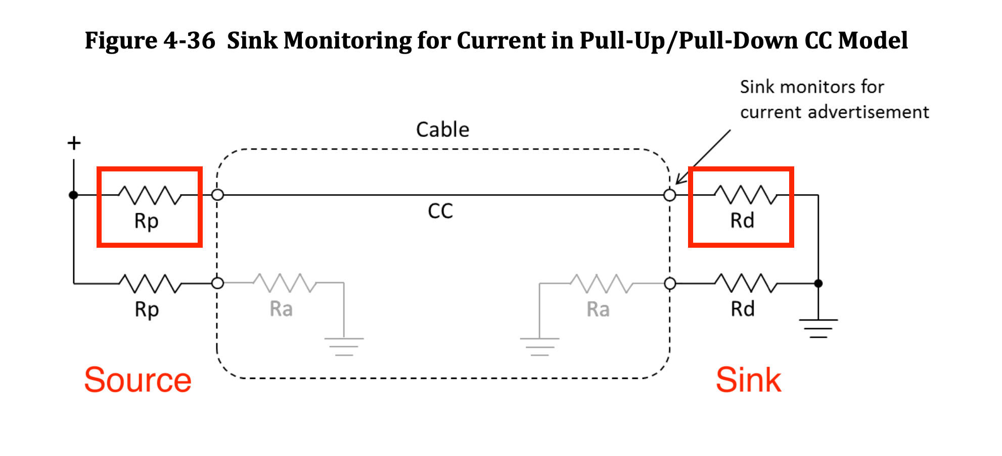 CC line inside a USB-C cable. Image from [1], red annotations by me
A USB-C source uses a pull-up resistor Rp to signal its current sourcing capabilities. Conversely, a sink uses a pull-down resistor Rd as a CC line termination.
Note how there are two CC pins, but a single CC line in the diagram above. This is because the plug is reversible – CC1 and CC2 are in opposite, symmetrical sides of the connector. The USB-C cable itself has a single CC line that connects either CC1 or CC2 at one side to either CC1 or CC2 at the other end.
Sources choose values of Rp to signal their maximum available current. Table 4-27 in [1] contains valid values of Rp. We makers most often design sink devices – we use USB-C to power our boards, charge our batteries – and for us the situation is surprisingly simple: all we need to do is to slap two 5.1 kΩ pull-down resistors between CC1 and CC2 and GND, and we’re in business for pulling up to 3 A from a USB-C source.
If you look up some open hardware schematics that use USB-C as a sink, chances are you’ll spot those lil’ 5.1 kΩ resistors. Here’s the USB-C schematic for Adafruit’s Feather RP2040:
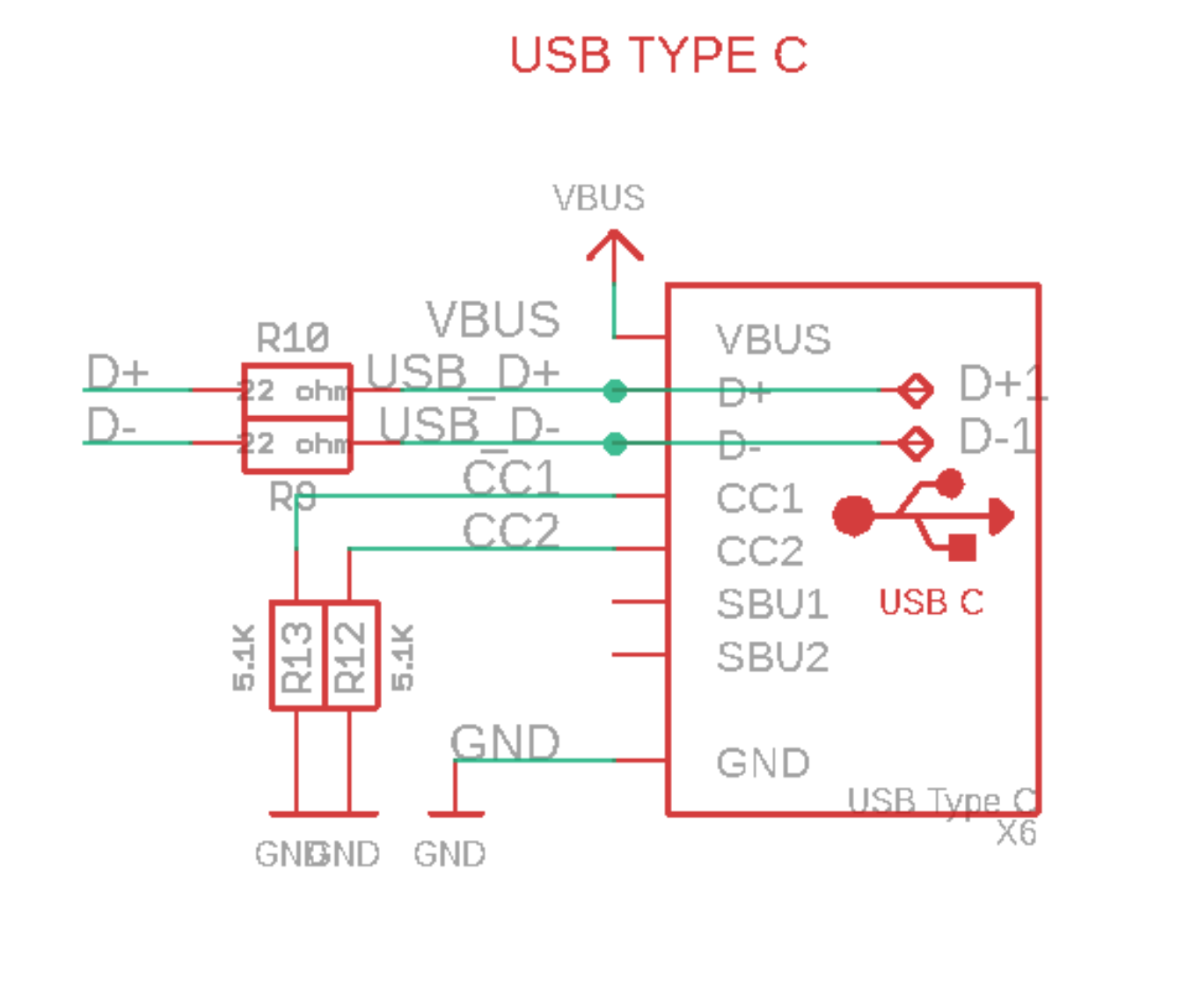 Section of the Feather RP2040 schematic
And for the new ESP32-C6-DevKitC-1 development board from Espressif:
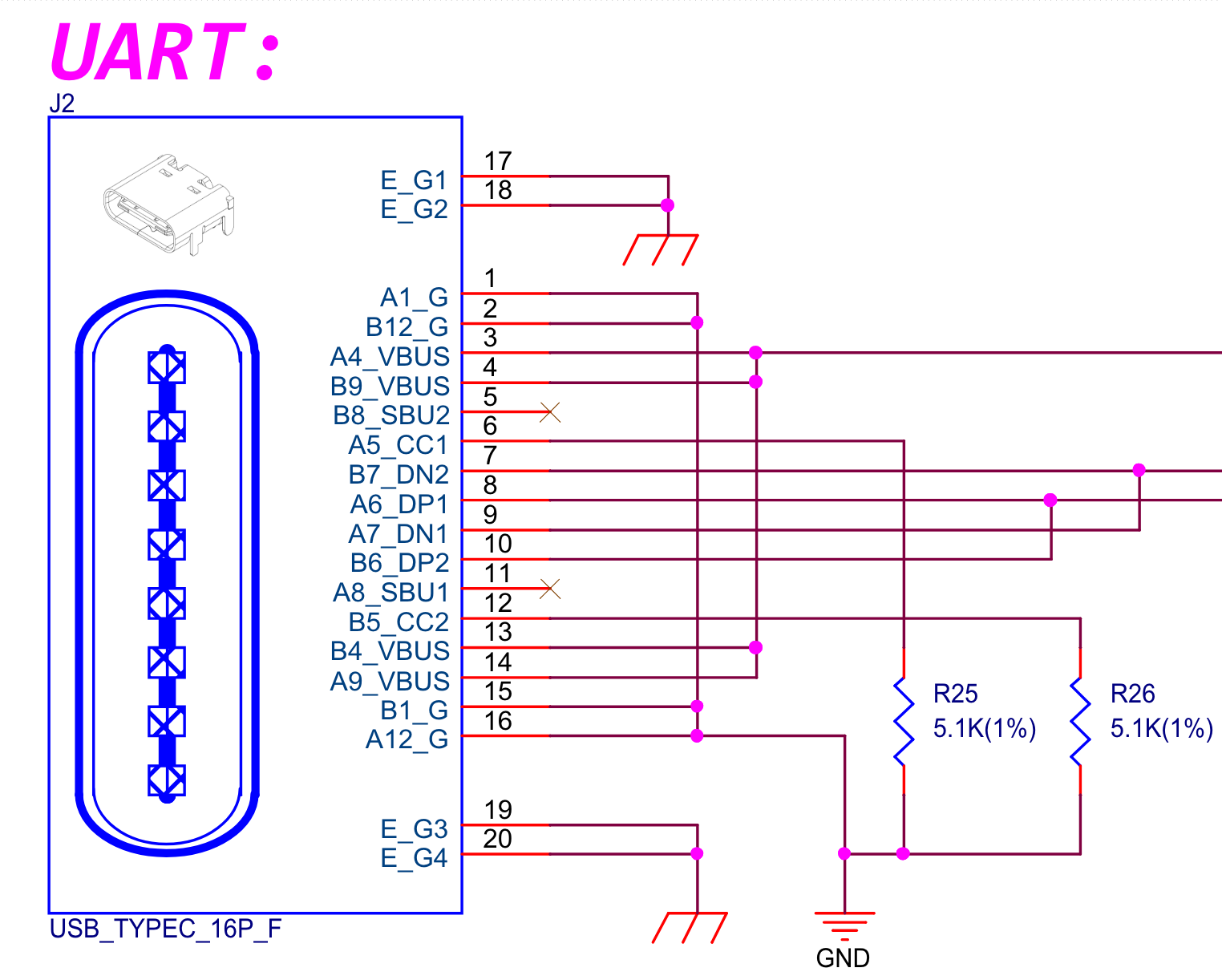 Section of the ESP32-C6-DevKitC-1 schematic
Somewhat reassuringly, sometimes even the greats get it wrong. But this is a pretty sweet deal: they get two resistors and we get 3 A at 5 V. This is very often all we need: we step it down to 3.3 V for our microcontroller and use it to charge our 4.2 V LiPo cells.
This is where things get more interesting. The USB-PD spec defines a way to negotiate even higher currents and other voltages than the 5 V we discussed until now. As of writing, the latest USB-PD 3.2 spec [2] offers us up to 5 A of current and 48 V, for a whopping 240 W of power.
Over the past couple of years I’ve been more interested in ultra-low power, tiny battery-operated devices, so I found it helpful to put these values in perspective:
| Device | Power |
|---|---|
| USB 2.0 port | 2.5 W (500 mA @ 5V) |
| USB 3.2 port | 4.5 W (900 mA @ 5V) |
| Philips Hue Smart Bulb | 10 W - 16 W |
| USB Type-C (non-PD) | 15 W (3 A @ 5 V) |
| 300 RGB LEDs strip @ 12 V | 50 W |
| Mini fridge | 60 W - 100 W (average) |
| MacBook Pro 16” (2023) fast charging | 140 W (5 A @ 28 V) |
| USB-PD 3.2 max power | 240 W (5 A @ 48 V) |
| RTX 4090 high-end graphics card | 450 W |
USB-PD
Okay, now we’re ready to get to the meat of the post. The question we’ll answer is: how do I get those sweet 240 W out of a USB-C Power Delivery port?
As in the previous section, the solution will include the CC lines. But now, instead of fixed resistors, we will have to do a little dance involving back-and-forth signals between the source and sink.
The Physical Layer
The USB-PD communication happens over the CC line. Section 4.6.2.4 [1] contains the following diagram:
 USB-PD BMC controllers diagram. Image from [1]
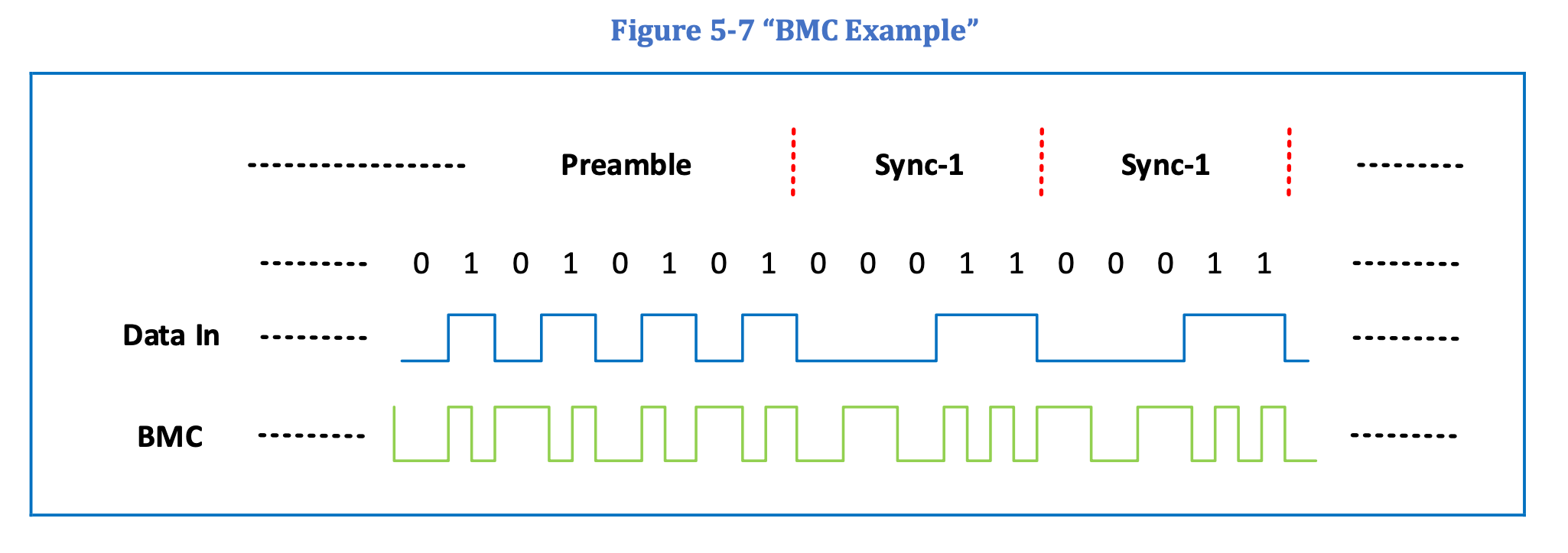
Now, in addition to the Rp and Rd resistors from before, both the source and the sink have PD controllers. BMC (bi-phase mark coding) is the physical coding scheme that dictates how logic 1s and 0s are represented on the wire. It’s an interesting topic on its own how it combines both data and clock in a single signal. For us, it suffices to know that 1s and 0s are represented as transitions between two voltage levels on the CC line – this page explains it well.
Figure 4-39 [1] shows a daunting example of a BMC signal over the CC line:
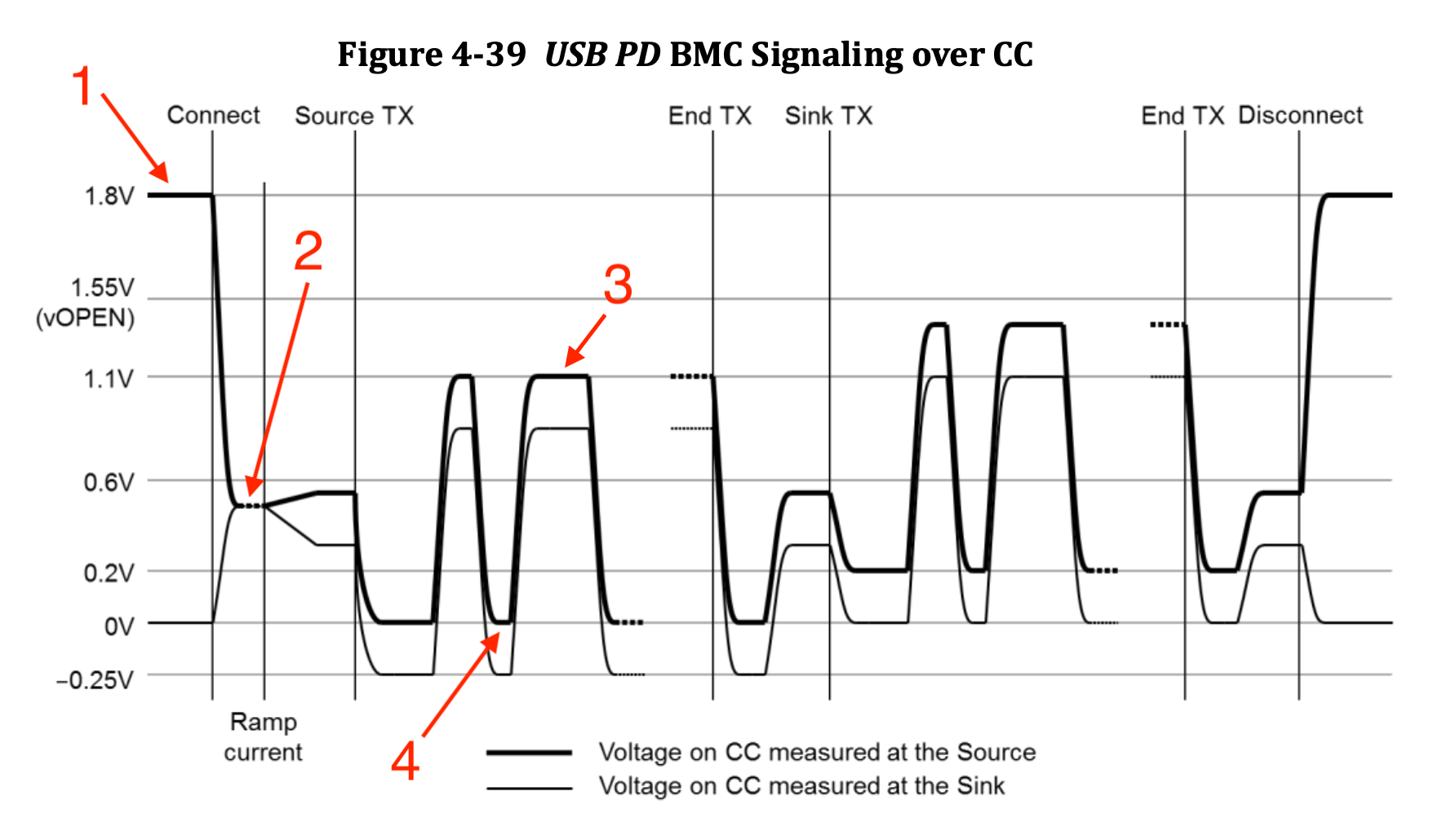 BMC example. Image from [1], red annotations by me
Oof – what’s with all those different voltage levels? Let’s focus on the bold black line, the voltage measured at the source’s CC pin. Prior to cable attachment, the source’s CC line hovers at 1.8V (1). Once the cable is connected, the CC line settles at around 0.5V (2), because the sink now forms a voltage divider. This level (2) is the baseline DC voltage of the attached CC line. The actual BMC signal operates between a high level of roughly 1.1V (3) and a low level of around 0V (4). Not so bad.
For practical purposes, the BMC signal in the CC line is a digital signal between 0V and ~1.2V. In [2], we see some diagrams representing the BMC signal as such:
 BMC as a digital signal. Image from [2]
Capturing the BMC Signal
We can hook up the CC line to an oscilloscope and marvel at the BMC signalling scheme. But if we want to decode the signal to inspect and debug it – which will prove itself crucial to our implementation later on – we better also pipe the signal to a logic analyzer.
The only logic analyzer I have around is a cheap knockoff that will straight up not have a good time dealing with 1.2 V as logic high. Before hooking it up, we must amplify the BMC signal to operate between 0 and 3.3 V-ish instead.
A smarter person would probably use an op-amp for this. I had a friendly MOSFET already stuck on my breadboard and used it to make a common source amplifier:
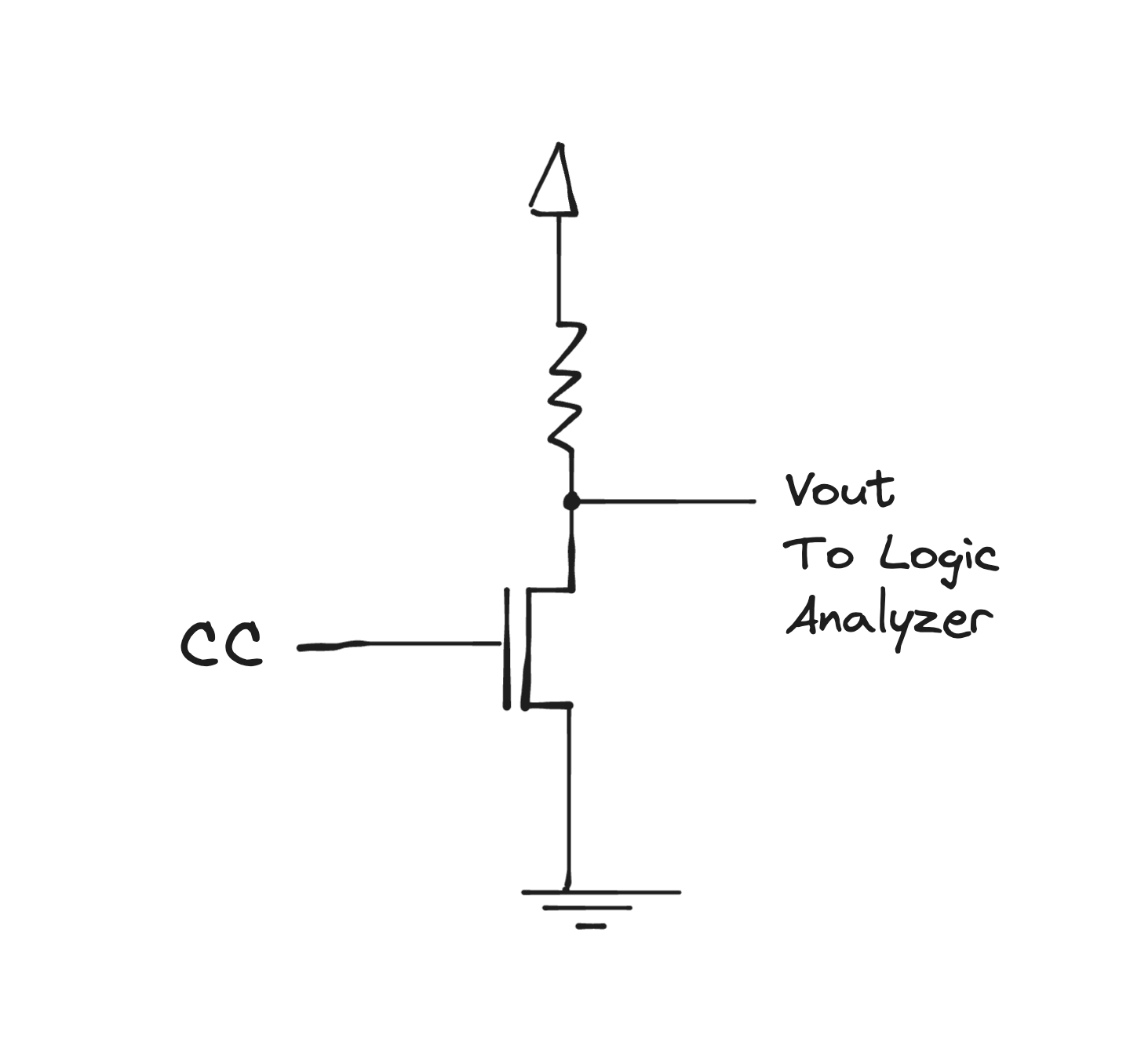 An N-channel MOSFET common source amplifier
I experimented a bit and settled on an ALD1103 and a 10 kΩ resistor:
How does the amplified signal look? Somewhere between bad and terrible. The rise and fall times for this setup are very slow for the 300 kHz BMC signal. Here you can see the original BMC signal in yellow and the amplified signal in blue:
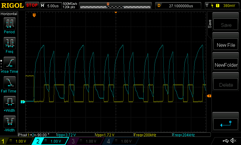 Oscilloscope capture of the BMC signal and its poorly amplified version
Although I wouldn’t put this in a real project, and it pains me to look at it, it kind of achieves the goal: the voltage swings are at least large enough to satisfy the logic analyzer thresholds. We’re also inverting the signal, but – lucky us – the BMC coding doesn’t care about that.
Believe it or not, this hack worked well enough that I didn’t think about it throughout the rest of the project, so I will call it a success. Really nothing as permanent as a janky, temporary solution.
Either way, we now can capture and analyze the BMC signal with our logic analyzer and hopefully decode those 1s and 0s into USB-PD messages. Luckily, some folks already built a BMC decoder that we can use: the PD3.1-analyzer. This plugin for the Saleae Logic software will decode our amplified BMC signal into USB-PD protocol messages.
The Protocol Layer
With the physical layer sorted out – that is, how 1s and 0s are encoded on the wire – , we can now turn to the protocol layer. This layer defines the types and contents of the messages exchanged between the source and the sink to negotiate power.
Let’s make things more concrete by looking at a basic example. Here’s a simplified high-level overview of a typical exchange between a source and a sink in USB-PD 2.0:
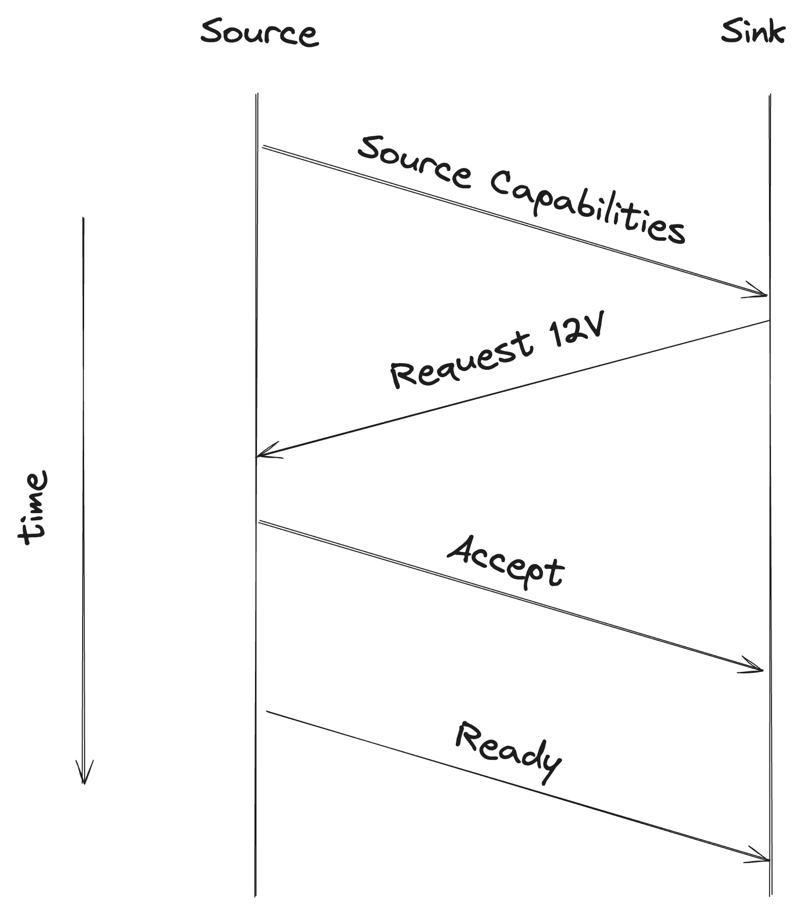 A basic, happy-path USB-PD 2.0 negotiation
With that exchange in mind, we will look in detail at these messages. But first, let’s talk about what’s common between all of them.
Every USB-PD message will contain the following parts (section 5.6 of [2]):
| Part | Size (bits) | Description |
|---|---|---|
| Preamble | 64 | A fixed sequence of alternating 0s and 1s. Used to signal the start of frame and clock to the receiver (see Syncword) |
| SOP | 20 | Start of Packet. A sequence of 5-bit symbols that represent to whom the message is addressed to |
| Message Header | 16 | Contains the message type and the number of data objects. A Data Message will contain one or more data objects; A Control Message has zero Data Objects |
| [Optional] Data Objects | 32 each | Optional message payload. Its interpretation depends on the message type |
| CRC | 32 | Cyclic Redundancy Check |
| EOP | 5 | End of Packet. A fixed 5-bit symbol that lets the receiver know the message is over |
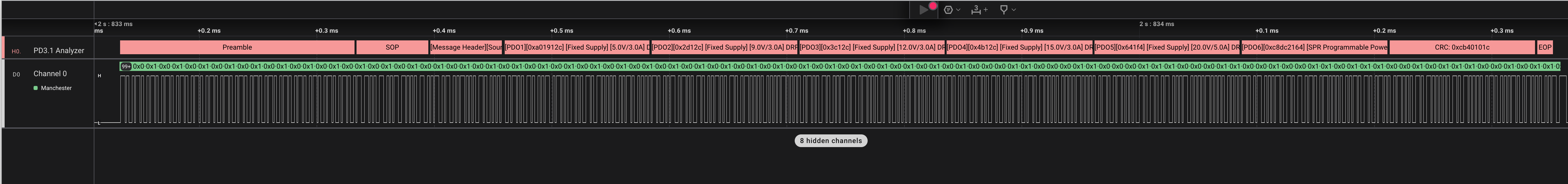
In the following logic analyzer capture, you can see those parts in a USB-PD message:
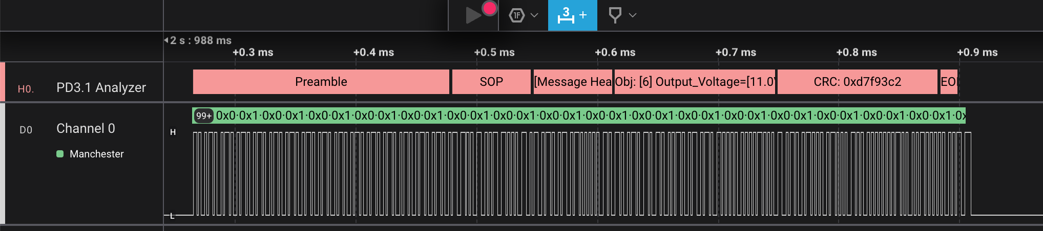 Logic analyzer capture and decoding of a BMC signal. This is a PD message requesting power from the source
From now on, we mostly care about the Message Header and the Data Objects, as, for our purposes, the other components are either constant or determined from it. Let’s go back to the example messages and see what they contain.
Source Capabilities Message & PDOs
This message is sent by the source to advertise its power capabilities. It goes by the name of Source_Capabilities (section 6.4.1 of [2]). The message contains a list of Power Data Objects (PDOs) in the Data Objects part of the message. PDOs are an important currency in USB-PD, and a term that pops up everywhere. Let’s spend some time understanding them.
Each PDO describes a specific power profile that the source can provide. Take a look at this photo of my Anker charger:
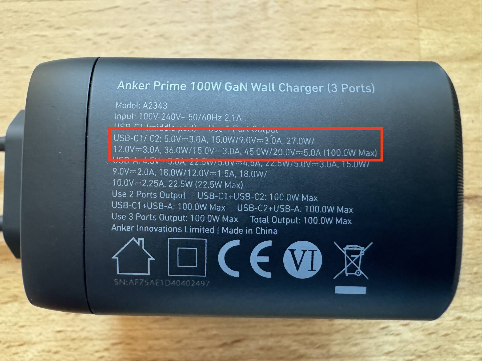
And here’s the Source Capabilities message from the same charger:
Not the easiest to read, but we can see the same data in table format:
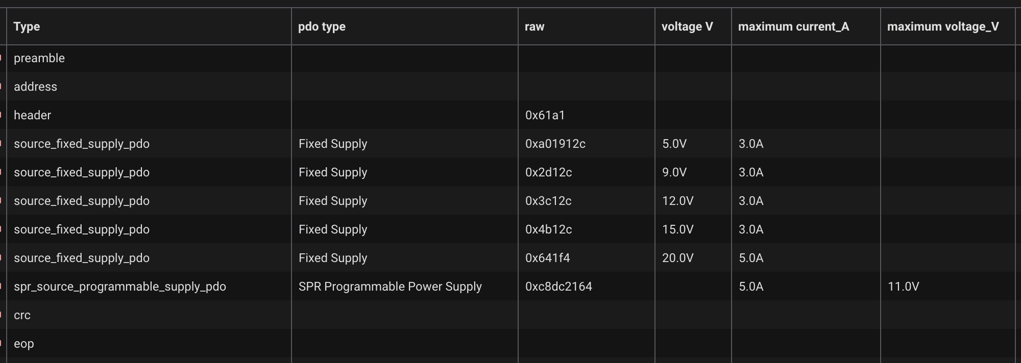
Aha! We see the same information printed on the charger in the form of its advertised PDOs. But if you look closely to the last PDO, you will see that it’s not like the others. Whereas the first five PDOs are indeed as printed on the charger – i.e.: fixed voltage – the last one is a Programmable Power Supply (PPS) PDO – a USB-PD 3.0 feature.
This particular PPS PDO allows us to request a voltage between 3.3V and 11V in 20 mV steps. This can be very interesting for makers, as we will see later.
Other PDO types are possible. This is the Source_Capabilities message from a 140 W UGREEN charger:
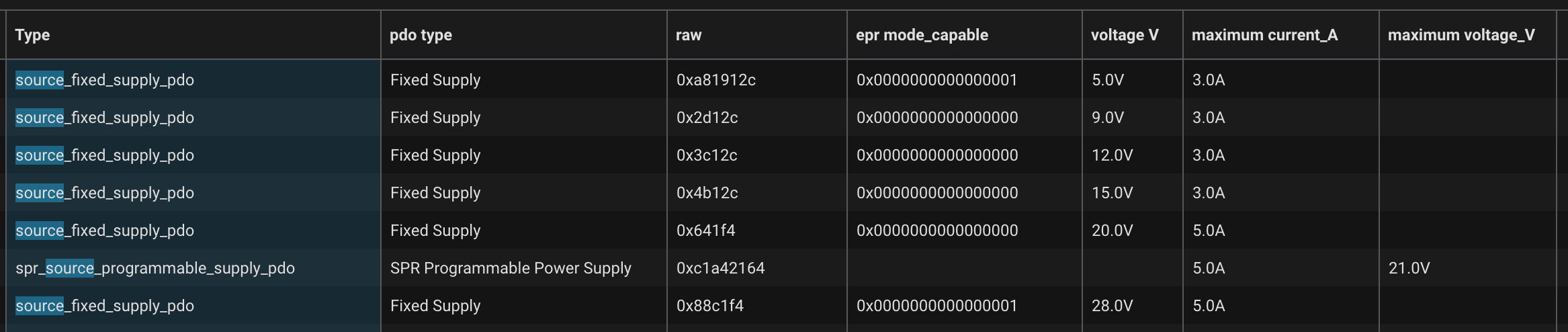
This one offers a PPS PDO of up to 21V. But it also offers something even juicer: a 28 V @ 5 A fixed PDO for a total of 140 W. This is supported by a USB-PD 3.1 feature called Extended Power Range (EPR), which lets us go over the 100 W limit of USB-PD 3.0 PDOs.
It is through these Extended Power Range PDOs that the USB-PD 3.1+ spec lets us pull the maximum power of 240 W, from a 48 V @ 5 A PDO. There also exists the Adjustable Voltage Supply (AVS) PDO, letting us request fine-grained voltages in the Extended Power Range domain.
As of writing, I haven’t managed to get any AVS nor EPR-capable sources with PDOs over 28 V to play with. There are some EPR-capable chargers offering 28 V @ 5 A out there, such as the 140 W Macbook pro 16” charger and the UGREEN 140 W. Some will advertise higher wattages, like the UGREEN 200W, but it just means total wattage – the maximum power per port is still 100 W.
The new Framework 180 W charger is the only one I am aware that offers up to 36V @ 5A, and supports AVS mode between 15 - 36 V. It looks pretty sweet, but sadly it does’t seem to support PPS PDOs. So we’d be out of luck if we needed, say, 7 V.
Request Message
After receiving the source’s PDOs via the Source_Capabilities message, the sink will elect one of them and send a Request message (section 6.4.2 [2]) to the source. There are variations of the contents of this message depending on the PDO we want to request. In the Extended Power Range domain, a separate message EPR_Request (section 6.4.9 [2]) is used altogether.
Table 6.26 [2] shows us how to request a PPS PDO by building a PPS Request Data Object (RDO):
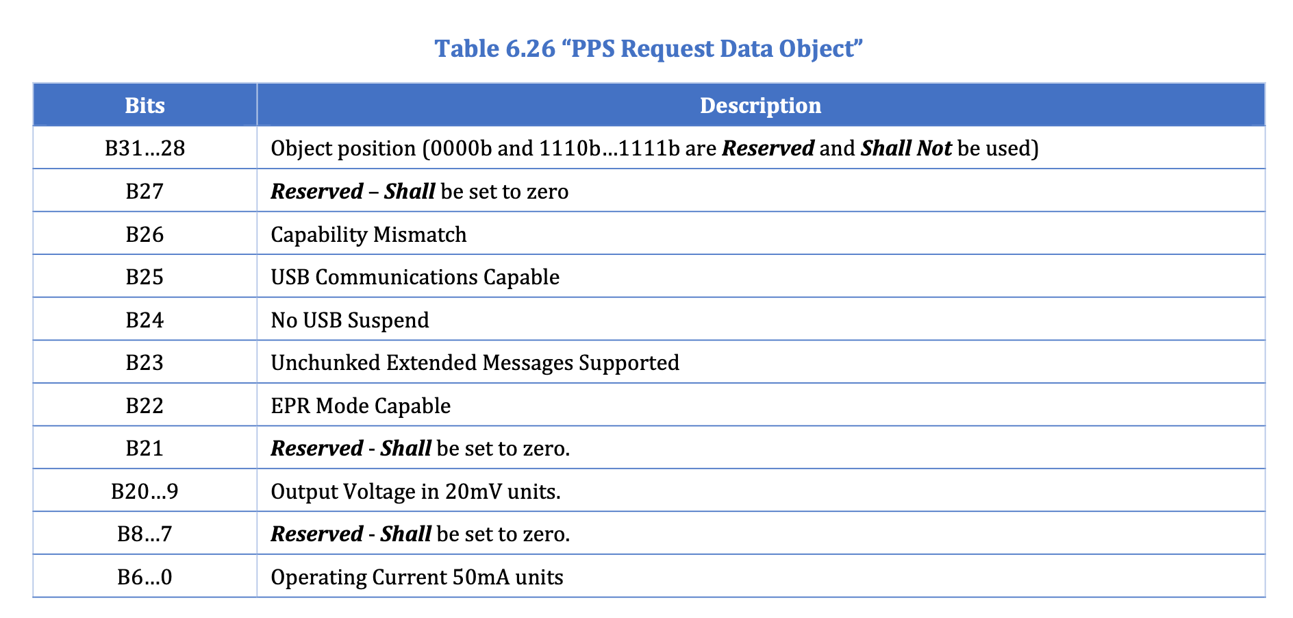 PPS request message. From [2]
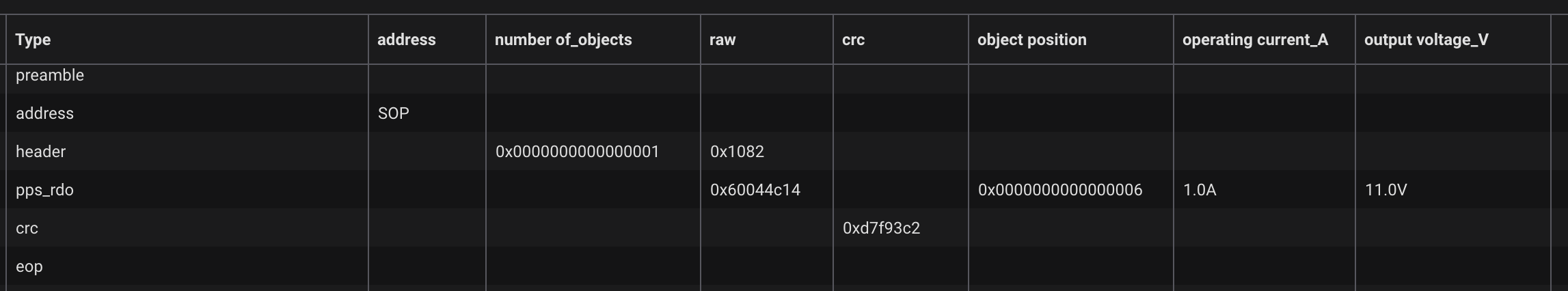
Here’s the raw message I used to request 11 V @ 1 A from the Anker charger above:
For us the most important fields are:
- Object Position: 6, as we’re requesting the 6th PDO
- Output Voltage: set to 11000 mV / 20 mV
- Operating Current: set to 1000 mA / 50 mA
Let’s double check if our decoder’s raw value above matches our expectation:
>>> hex(6 << 28 | (11000 // 20) << 9 | (1000 // 50) << 0)
'0x60044c14'
Accept & Ready Messages
If all goes well with the Request message, the source will send back an Accept message (section 6.3.3 [2]). This is a Control Message, meaning it has no Data Objects. Shortly after, the source will send a PS_RDY message (section 6.3.6 [2]) to signal that the requested voltage is now present on the bus.
Some Other Message Types
The spec defines many other features backed by many other message types. Some examples:
| Message Type | Description |
|---|---|
Get_Source_Cap |
Sent by the sink to request the source’s capabilities |
Soft_Reset |
Sent by either source or sink to signal a reset in the USB-PD logic, often due to communication error |
Reject |
Sent by either source or sink to signal a failure to fullfil a request |
Other messages are used to support more advanced features like Power Swap, in which the source and the sink exchange roles. Figure 8-135 [2] contains an authoritative state machine for the sink, and while it’s a bit intimidating, it is a great reference.
Extended Messages
Longer messages may be split into multiple chunks. This is signaled by the Extended bit in the Message Header (section 6.2.1.2 [2]). The receiver is expected to repeatedly request the next chunk and rebuild the message from them.
Some Raw Logic Analyzer Captures
I dumped some full captures of the USB-PD negotiation with different PDOs and sources in this repo. Some interesting cases:
- anker100w-pps-11v-too-much-logging-failure.sal: what happens if we take too long to respond to a
Source_Capabilitiesmessage - ugreen140w-epr-fixed-28v-success.sal: a successful negotiation of an EPR PDO, together with chunked extended messages
Timing Matters
Many USB-PD operations are time-sensitive. For example, after receiving a message that expects a response, the sink has roughly 30 ms (tSenderResponse, Section 6.6.2 [2]) to respond. Sometimes even adding a bunch of log messages may cause us to miss this deadline, causing a failure in the negotiation and a hard reset from the sender.
I captured one of those failures in anker100w-safe5v-fallback-success-then-failure-too-much-logging.sal. In this scenario, after a successful negotiation, the source still sent some unsolicited Source_Capabilities messages, to which I couldn’t respond in time because I was too busy celebrating the succesful negotiation with STDOUT.
Some other timers are worth mentioning:
| Timer | Section | Description |
|---|---|---|
tPPSTimeout |
6.6.19.2 [2] | When negotiating a PPS PDO, we need to periodically se-rend the same Request at least each 12 seconds. |
tSourceEPR KeepAlive |
6.6.21.3 [2] | When operating in the Extended Power Range domain, the sink must send an EPR_KeepAlive message at least every 750 ms |
The Current Limit
While USB-PD 3.2 goes up to 240 W, there is a global upper limit of 5 A for the current. This means two things:
- If we want higher power, we must increase the voltage, up to the maximum of 48 V
- At lower voltages, we don’t have as much room for power. At 12 V, we can pull a maximum of 60 W
USB-PD Sniffers
gregdavill/PD-sniffer and dojoe/Twonkie are DIY-friendly reimplementations of Chromium project’s Twinkie. These are boards that place themselves between source and sinks, decode and dump the USB-PD messages between them.
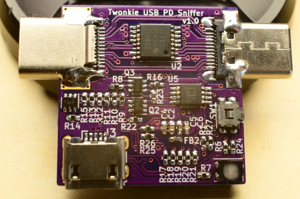 The Twonkie USB-PD. Image from dojoe/Twonkie
I haven’t built those, mostly because I didn’t know they existed when I started this project, but they make sniffing the USB-PD messages considerably easier than using an amplifier and logic analyzer like I did here. If you’re only interested in the protocol layer and above, these seem like excellent choices.
Software References
The Ralim/usb-pd contains a great implementation of a USB-PD sink stack using the FUSB302 IC for the physical layer. It was extracted from the also excellent Ralim/IronOS, an open source firmware for USB-C soldering irons – one of the first places where USB-PD started shining for makers.
Clara Hobbs’ work on PD Buddy Sink also laid the groundwork for many other USB-PD projects.
Introducing: GIMME DANGER!!
I wanted to try my hand at designing a USB-PD board and the software stack to go with it. The idea was to build a all-in-one board that would let me pull power from a USB-PD source and use it to power LED strips and other smart home devices through ESPHome and Home Assistant.
All hardware design files and software are available in the rbaron/gimme-danger.
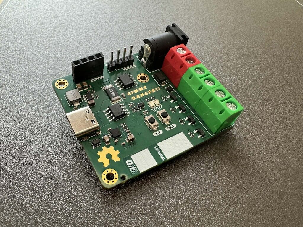 GIMME DANGER!! PCB front
The Hardware
- ESP32-S3 module
- FUSB302B USB-PD controller
- INA219 current sensor
- 5 output PWM channels
- 2x5.5mm barrel jack for raw output voltage access
- Optional OLED display
The PWM drivers are rated for 30 V. The FUSB302B is only rated for 20 V, with an absolute maximum of 28 V. Although I have been using it with EPR mode @ 28 V, the safe voltage limit is 20 V. As EPR USB-PD gets more popular, I hope we start to see more controllers that are rated for higher voltages and accessible to makers.
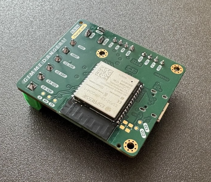 GIMME DANGER!! PCB back
When designing a USB-PD capable board, we need to pay attention to details that are not as critical in the low-power boards I’m used to build. I highly recommend this video from Phil’s Lab on USB-C Power Delivery Hardware Design. I am an absolute fan of his channel and always learn a lot from his videos.
The Software
I implemented a custom ESPHome component to handle the USB-PD negotiation through the FUSB302B. The FUSB302B handles the physical layer, and its the component’s job to build the messages, timers, and state machines to negotiate power with the source.
The custom fusb302 component lives in the ESPHome fork github.com/rbaron/tree/fusb302. To use it, all wee need is to import the external_component into a typical ESPHome YAML config file. For example:
external_components:
  - source:
      type: git
      url: https://github.com/rbaron/esphome
      ref: fusb302
    components: [fusb302]

fusb302:
  voltage: 11000 mV
  current: 1000 mA
  start_power_negotiation_on_boot: false
  on_pd_negotiation_success:
    - lambda: |-
        ESP_LOGW("fusb302_trigger", "PD negotiation success outcome: %d", success);
  on_pd_negotiation_failure:
    then:
      - lambda: |-
          ESP_LOGW("fusb302_trigger", "PD negotiation failure outcome: %d", success);
Beside the ESP32-S3 in GIMME DANGER!!I, also tested this component succesfully on a regular ESP32 board, a ESP32-C6 board and an RP2040 board. I would love to contribute this component upstream, but with the high power involved and the potentially costly side effects of bugs, I would be more comfortable if more experienced folks used it first before advertising it to all users.
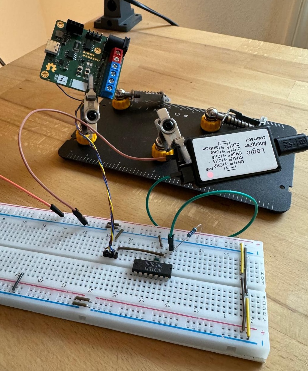
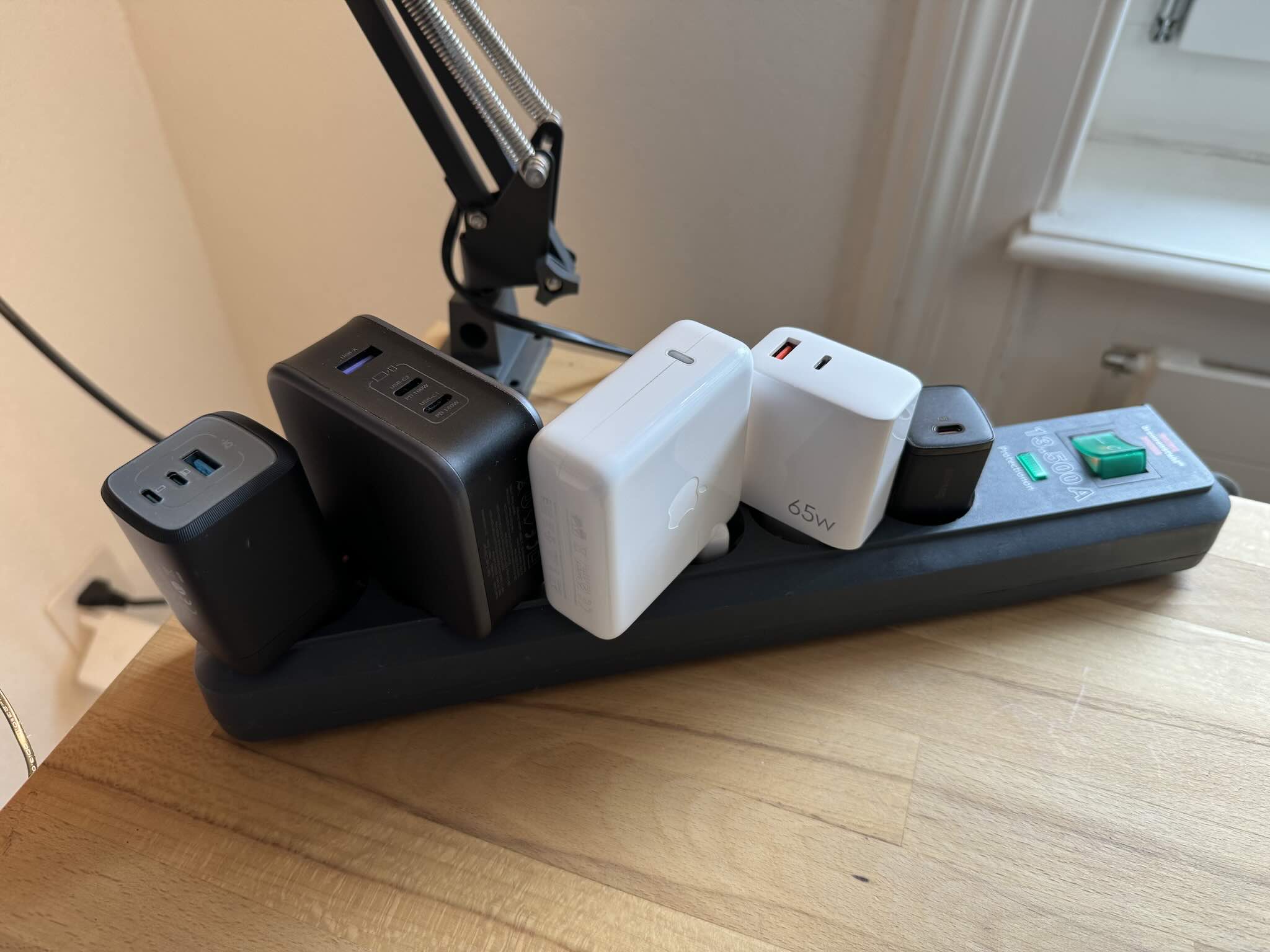
I also tried to test the implementation on a bunch of different USB-PD sources – some of them are kinda liberal with the specs. Here’s my humble test bench:
Demos
12 V LED Strip
Here’s GIMMER DANGER!! controlling a 12 V LED strip through Home Assistant:
A Makeshift Programmable Power Supply
With the PPS PDOs, we can request voltages in a fine grained manner. We can even change the voltage on the fly. Here’s a potentiometer controlling the voltage set point, and a button that triggers the USB-PD power negotiation for that set point:
A WiFi-Controller Power Supply
Here’s a terrible and fun idea: a Power Supply that you can control through Home Assistant:
A 12 V RGB LED Strip
The code for all demos are in rbaron/gimme-danger/tree/main/code/esphome.
Docs
- [1] USB Type-C Spec R2.3 - October 2023
- [2] USB Power Delivery Specification Revision 3.2, Version 1.0 - October 2023