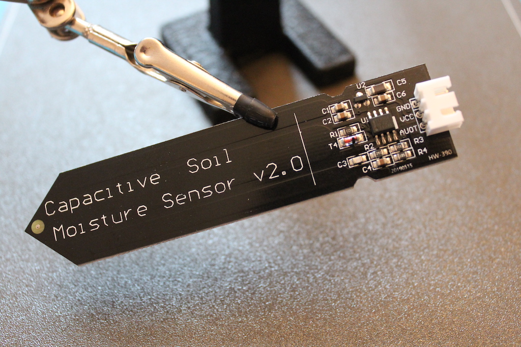
These soil moisture sensors are incredibly interesting. We stick them in the ground and - magic! - it outputs an analog signal that is proportional to how wet the soil is. By looking under their hood, we’ll demystify how they work and, I promise, it will be beautifully simple.
A Simple Resistor and Capacitor Circuit
At its heart, a resistor and a capacitor work together to estimate the amount of water in the environment around them. We can represent this RC circuit as the follows:
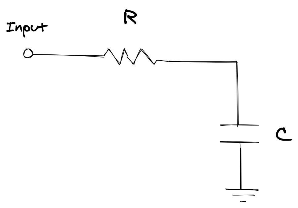
In any RC circuit like this one, if we apply a positive voltage to the Input, the capacitor C will start charging up through the resistor R. As charges start to accumulate on the capacitor’s terminals, the voltage across C starts to rise.
For example, if we apply a step of 5V to Input, the voltage across the capacitor will behave like this over time:
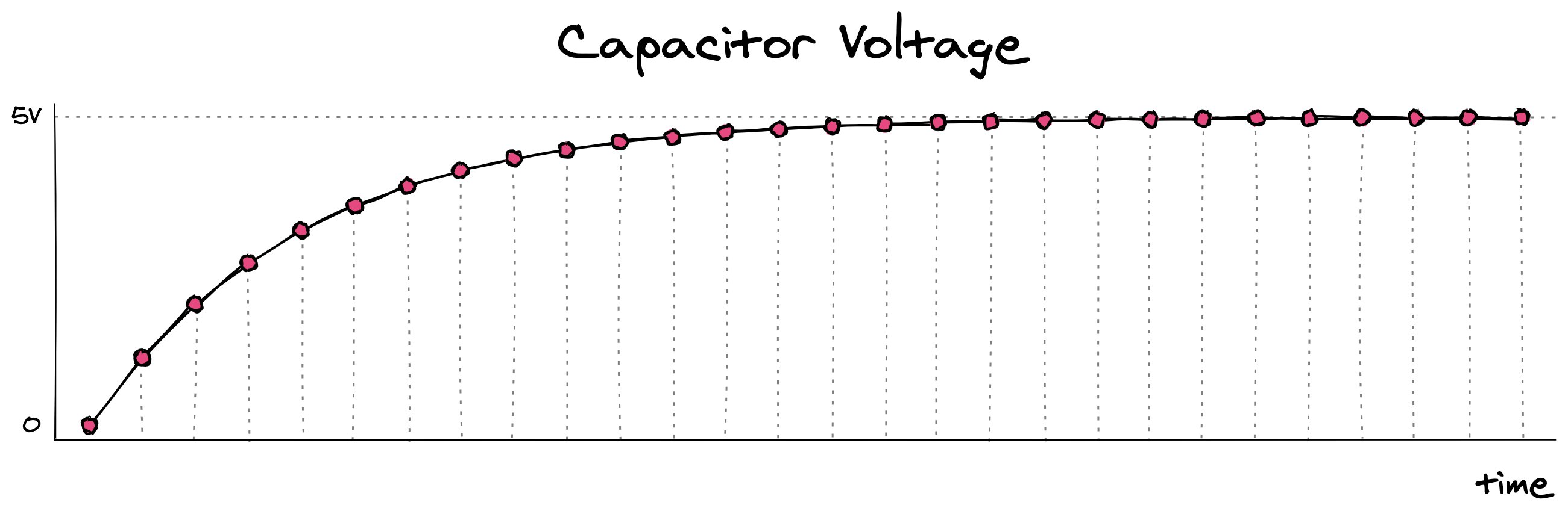
The general shape of this curve is characteristic of RC circuits. By changing the values of the resistor and the capacitor, we can control how fast or slow this voltage rises towards 5V. Here for example, we can keep R constant and try out two different capacitance values for C:
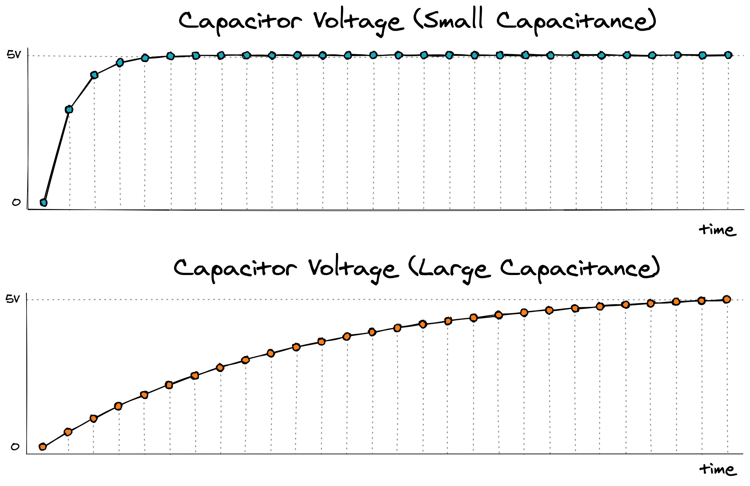
Intuitively, we can think that the large capacitor (with larger capacitance) requires more charge units to reach the input voltage, and so it takes longer to charge up.
The Plot Twist
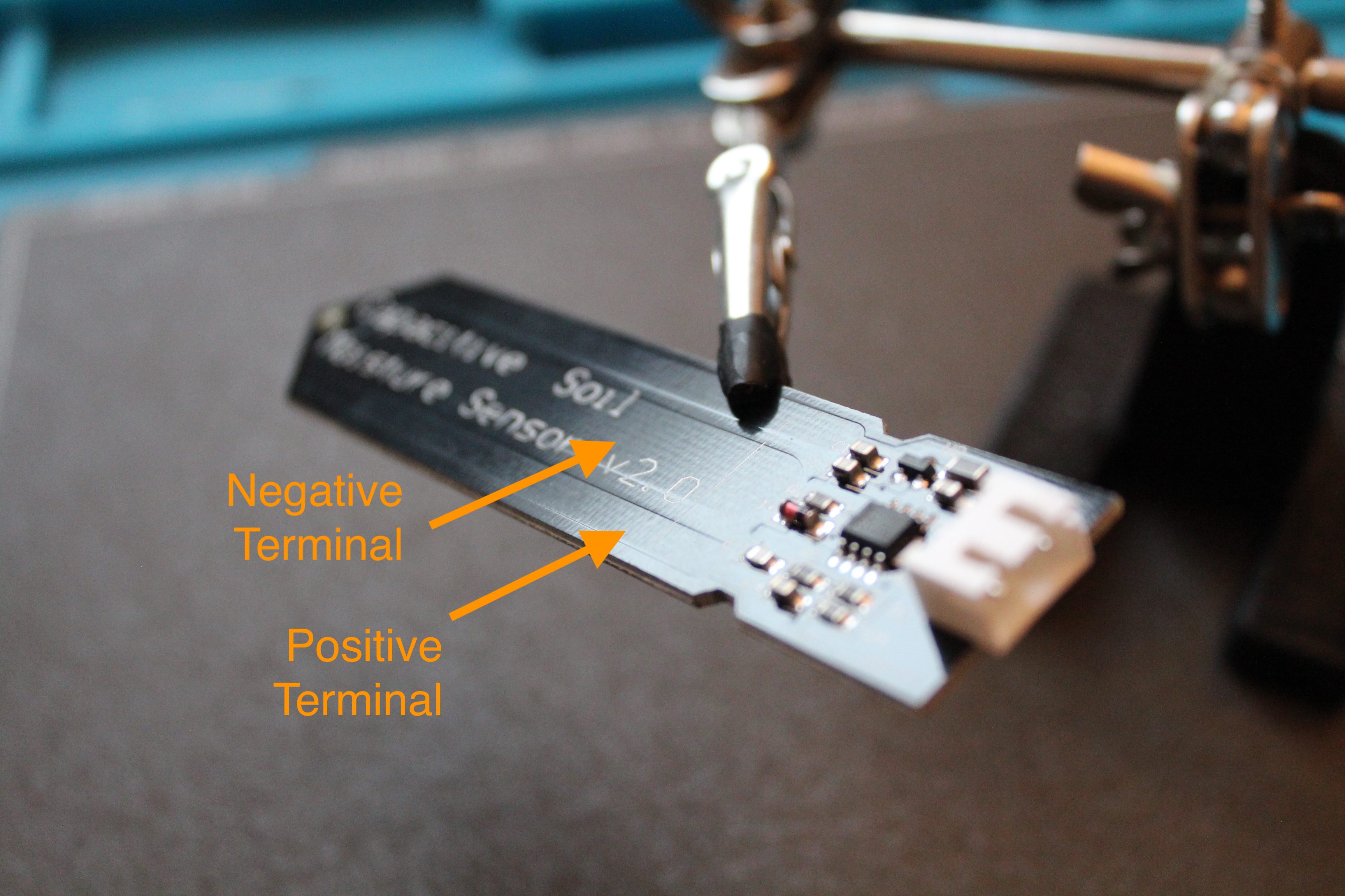
The astonishing part is that the capacitor C in the sensor board is not a real capacitor, but simply two copper traces that act like a capacitor! This “parasitic capacitance” effect happens all the time in circuits and it’s often neglegible and undesirable. But by making the two copper traces deliberately large, this cool effect can be cleverly exploited for good:
The last piece of the puzzle is that the actual capacitance of this crude capacitor (really, just two copper traces) depends on the shape of the traces and the environment around it (the technical term is dielectric).
You guessed it - if we change the environment in which these traces are inserted, we change its capacitance. And, as we saw before, changing its capacitance affects how fast the capacitor C in an RC circuit charges up.
In the video above, we repeatedly charge and discharge the capacitor C by applying a square wave at the Input. This lets us visualize the effect of varying the dielectric of the parasitic capacitor: when out in the air, the capacitor C has smaller capacitance, so it charges up fast.
When inserted into the water, the capacitance C increases, and charging up the capacitor gets slower. This is why we see “smaller” (peak-to-peak) waves in this case. The remaining components in the sensor board are responsible for generating this square wave and detecting the peaks of this RC charging curve.
b-parasite
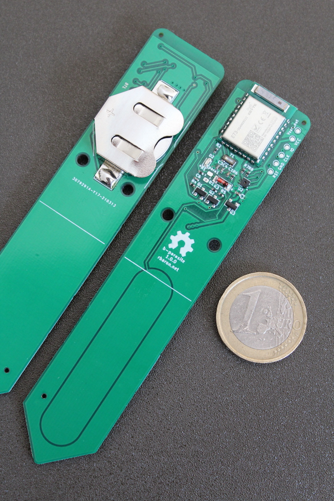
I put these principles to work on b-parasite, an all-in-one soil moisture and ambient temperature sensor. It periodically broadcasts its sensor data via Bluetooth Low Energy. It’s completely open hardware and open source, so you can build your own - check it out!