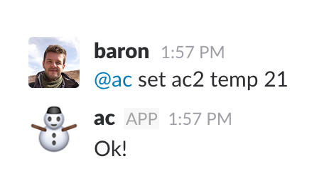
@ac bot in action on Slack
In this post, I’ll try and talk about the building process of a system for controlling two of our office’s Air Conditioner units via Slack. It turned out to be really fun to build and, differently from virtually my side projects, surprisingly useful! This will be an overview of some of the interesting things that came up during the project. Please feel free to send me an email if you have any questions or suggestions.
System overview
On a high level, the idea was to build a system that receives messages sent from Slack and performs an action in the “real world”. The action is the actually controlling of the AC, via infrared commands, exactly like the ones its remote control emits.
I suppose there are more than a few ways to model such a system. We could, for instance, try and run the whole thing with just a microcontroller. That is, we could program the microcontroller to receive messages directly from Slack and process them as they come. I haven’t tried this approach, so I don’t know how well a low cost chip would be able to handle real-time processing for potentially many messages. I chose to have a “regular” computer program that connects to Slack’s real time API and also listen for connections from the microcontroller. The main reason, besides having more computing power, isn’t a technical one, but I also took this as an oppotunity to use technologies I wanted to try. Specifically, I wanted to experiment with clojure’s async channels and also understand a little better how clojure handles non-blocking IO. All the code is available and linked below.
The final architecture ended up as follows:
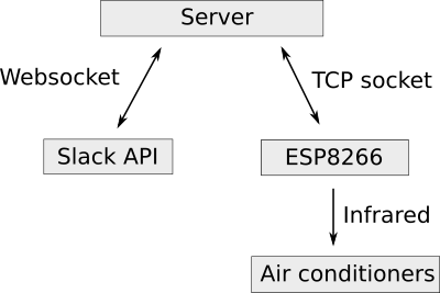
System architecture
The hardware
For the microcontroller, I chose the ubiquituous and loved (both for more than justified reasons!) ESP8266. It’s a low cost (< 10 USD) board with built-in WiFi and TCP stack, which makes it great for small projects that need network communication. Even nicer is the fact that we can program this board using a lot of the amazingly practical Arduino environment.
Having little knowledge about how both the ESP8266 and infrared (IR) work, the first step I took was to build a hacky development board for playing around. The pinout for the ESP model I have is not protoboard-friendly, so I ended up putting together a perfboard I could use to develop and test. This is the “Prototype #1” below. You can see the ESP board in the lower left, as well as the IR LED in the upper left. In the front, the black boxy component is a IR receiver, which I used both for debugging and copying the IR signals I wanted to reproduce. In the back, between the ESP and the IR receiver, there’s a 5V to 3.3V converter – the ESP runs on 3.3V. For programming I used a standard FTDI cable connected to the Tx/Rx pins on the ESP.
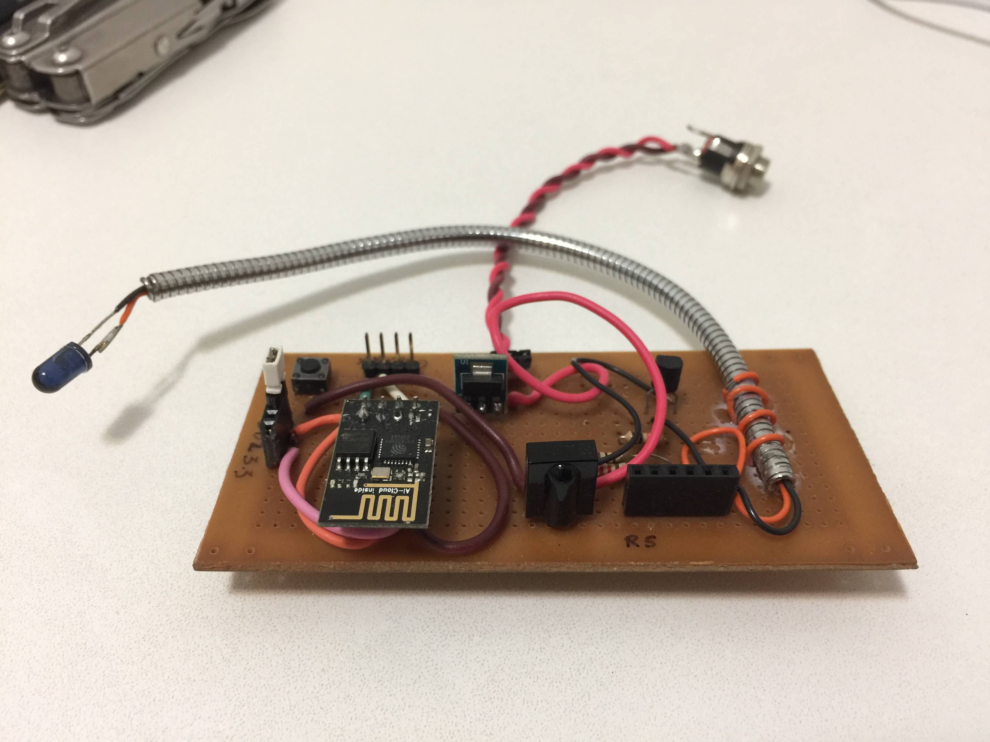 Prototype/development board #1
For the IR reading/writing machinery, I used the IRremote8266 library. It is an ESP8266 port of the original Arduino-IRremote library, which handles the low level signal generation and works nicely as advertized.
Copying the IR commands from the actual remote
There are two ways we can go about figuring what are the actual patterns the IR LED should emit in order to control a device. The hard, elegant way would be to understand the IR protocol the device uses. This means understanding what each “bit” means and how to construct a well formed message, which involves figuring out the meaning of all (or most) bits in a message, as well as often appending some sort of checksum. For an example, check out the decoding logic for the LG standard. This is a really interesting and challenging problem to tackle, but I decided I needed to get things working first. I also couldn’t find code on the internet for generating IR signals in this fashion for the brand I needed (Carrier).
The “chinese room” way, which I used, simply involves copying a signal and playing it back, like some sort of replay attack. This requires a somewhat tedious process of manually generating, reading and recording the signals we want to play back.
Here, there’s also a small caveat with the IR library I used. I spent more hours than I’d like to admit trying to get my copied signal to play back with no success. It would work for my TV, but not for the air conditioner at the office. It turns out that Carrier’s protocol uses messages of longer lenghts than the ones supported by the library. Once I figured out the reason, the fix was easy: I increased the size of the buffer used for recording signals here. Setting it to 255 allowed the whole signal to be recorded and the play back worked. All good!
Prototype #2
Once I had the initial version of the system up and running, it almost worked well. Although it did what I had expected initially, it wasn’t reliable at all. There were a few problems:
-
It wasn’t resilient to power outages, because I didn’t set up the proper pulling up/down of the pins for selecting the boot modes. More on this in the next section;
-
Having the board on the table and pointing the IR LED to the AC was a little annoying. Things would get in front of it, I would push it without noticing, or the table would move and the thing wouldn’t work. It is particularly simultaneously amazing and frustrating if we think the signal is, in a way, traveling all the way from another continent and failing to reach its destination in the last couple of meters…
-
There are two AC units in the main room, about 4 or 5 meters from one another. They’re the exact same model, so it seemed like a relatively small and incremental step to be able to control both units.
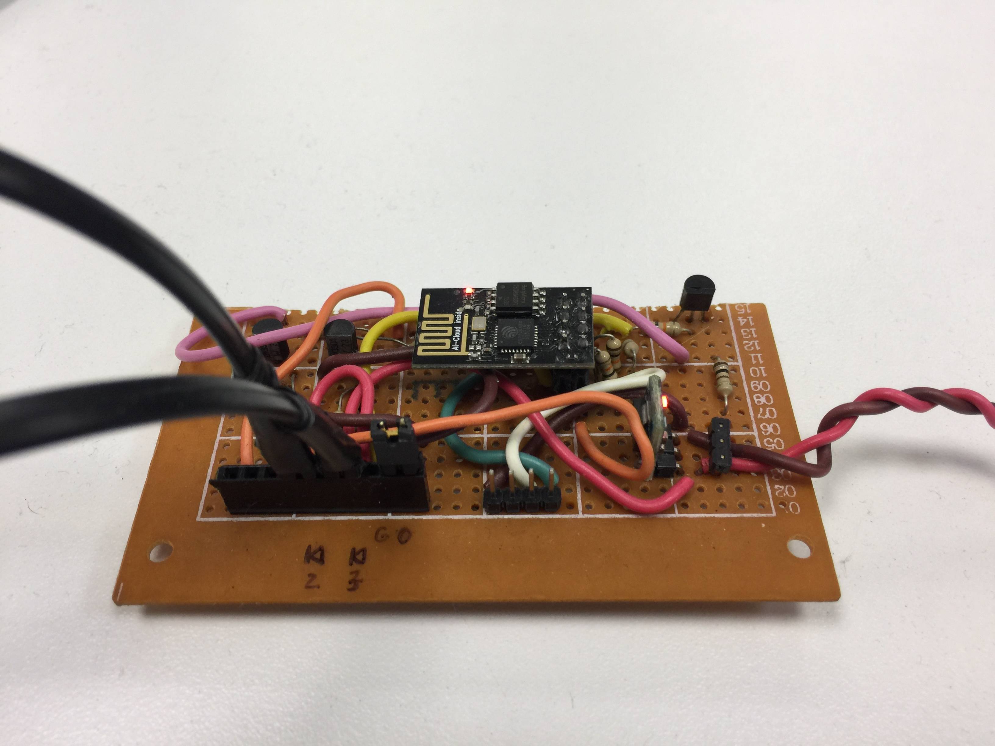 Prototype #2 - codename spaghetti
The prototype #2 is very similar to the first one, except it has two channels for hooking up two IR LEDs and it has no IR receiver. The IR LEDs are also not actually on the board anymore, but are instead hooked up externally with a connector. These are the two black cables on the lower left of the board.
As you might have imagined, I fixed the IR LEDs on the AC units themselves this time. As you might imagine, it looks totally ridiculous.
Schematic
The accompanying circuitry consists of a voltage converter – to feed ESP 3.3V from a 5V power supply – and two amplifiers for driving the IR LEDs. Usually, the maximum current outputed by a microcontroller port is significantly lower than the one you need to drive your load. In this case, each GPIO port on the ESP can output up to 12mA, while the load (the IR LED) works best with a current around 100mA. In this spirit, a transistor is added to the circuit, and the output GPIO pin is connected to its base. The transistor allows a bigger current to flow through the IR LED when a small current is present at its base. Check out the schematic below, specially the top connection.
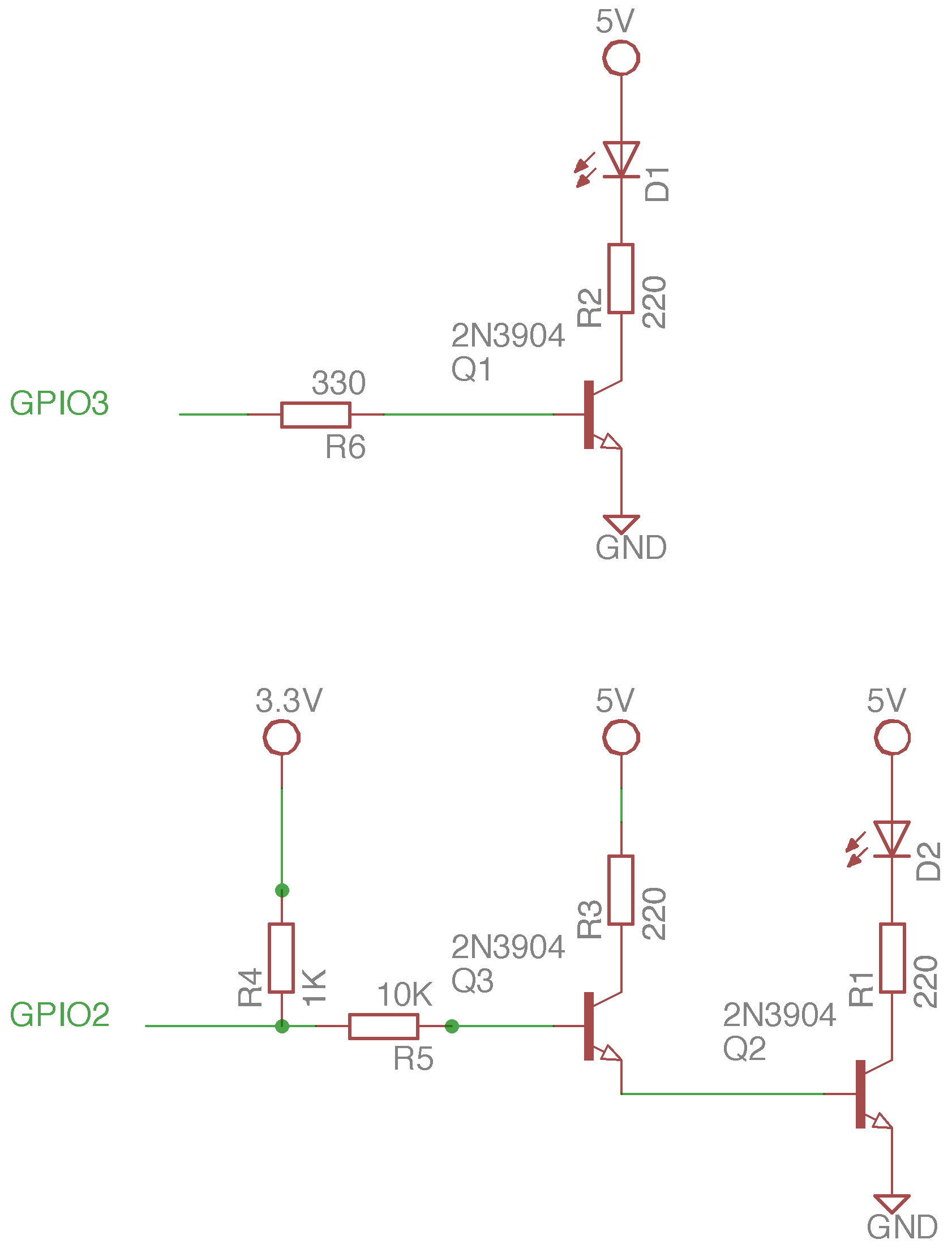
Schematic for Prototype #2
It might have bothered you that the circuits on the two channels are not symmetric. The reason for that is explained in the following optional section.
Optional detour - ESP8266 boot modes
We can boot the ESP8266 in different modes. Two of these modes are:
- Flash mode - In this mode, we can upload new programs to the ESP8266;
- Execution mode - In this mode, the ESP boots and starts executing the program we uploaded;
We can select the mode in which the ESP boots by powering it up with some pins connected to either 3.3V or GND. To boot in flash mode, we must connect the GPIO0 to GND (“pull down”) and GPIO2 to 3.3V (“pull up”). To boot in normal execution mode, we must pull both GPIO0 and GPIO2 up. In the development board, I simply added a jumper, which I used to pull GPIO0 down when I wanted to upload a new program. When we want our program to boot - and for the system to boot back up when there’s power outage - GPIO2 must be pulled up.
Since the ESP is a super low cost device, it has limited exposed GPIO pins. If we wish to use the GPIO0 and GPIO2 pins in our programs, we must guarantee that they’re going to be pulled up during boot. If you look at the top part of the schematic above, the GPIO3 is actually pulled down (by the NPN transistor’s collector). It doens’t matter, since the GPIO3 has nothing to do with boot mode selection. This won’t work with GPIO2, though. I think things would be better if we used a PNP transistor instead of NPN ones, but I also didn’t have any PNP transistor ready.
In order to guarantee that GPIO2 will be pulled up during boot, I hooked a pull up resistor of 1K between GPIO2 and 3.3V, and a base resistor of 10K between it and the transistor’s base. These resistors have the effect of acting like a voltage divider that will pull GPIO2 up. Cool, now we guarantee that GPIO2 will be pulled high during boot, but on the other hand, there’s now a 10K resistor on the transistor’s base, which means the current flowing through it will be really tiny, and the transistor won’t provide the amplification we need. In order to amplify the signal even further, we can add a second transistor, so it will amplify the amplified signal again. This configuration is called Darlington. I learned this trick here.
It’s also important to note that the GPIO3 is actually the same pin used for reading serial data in the ESP (Rx pin). The advantage of using this pin for sending data is that we don’t need to worry about messing up any boot mode selection, like we did with GPIO2 and would have to do with GPIO0. The disadvantage is that reading serial data in our program won’t work anymore. Since we don’t need to do read serial data anyway, we might as well save a transistor.
The software
ESP8266 software
Given the choice of architecture, the program running on the ESP itself has relatively small functionality. It was heavily based on the WifiClient example sketch. It has a set of hardcoded IR commands, such as “turn ac on and set it to 20 degrees Celcius”, or “turn AC off”, described as lists of time intervals. It also connects to the server via a TCP socket and has to decide if the received message makes sense and, if so, issue the appropriate IR signal to one of the two AC units.
Here there’s also an interesting problem that had to be solved. Unlike short lived HTTP requests, long lived TCP connections are trickier to maintain. The way it works is: the server listens for and accept new connections from the ESP. The ESP waits until there’s data to be read. A problem arises when there’s instability or lack of connection while the ESP waits for data. If the connection is abruptly interrupted, it means that there won’t be a graceful connection termination between the parties (since there’s no connection for sending the termination packages!), so the ESP could wait forever for new data, oblivious to the fact that there’s no connection anymore. The connection is “stalled” or “half open”. This caused the system to fail and become irresponsive.
In order to circumvent this problem, I implemented a rudimentar ping-pong message scheme. The server will send a “ping” message every few seconds and wait for a “pong” response. The ESP will expect a “ping” message every few seconds and respond with a “pong”. If the ESP doesn’t receive a message after the expected amount of time, it assumes the connection is stalled and reboots. The server assumes disconnection if it can’t send a ping or doensn’t receive a pong.
The ESP code can be found here. As for the odd project name choice, I didn’t think I’d ever make it public and made a terrible pun.
Server software
For the server, I chose clojure for the sole reason I wanted to practice and also experiment with the core.async library for coroutines (or “inversion of control threads” – IoC threads – as they call it).
The server’s main responsibility is to connect to Slack’s real time API, look for interesting messages (such as “@ac set ac2 temp 20” or “@ac set ac1 off”, where @ac is the name of the bot in Slack), and forward them to the ESP8266 over a TCP connection. It also handles the ping-pong scheme by sending a ping message to the ESP every few seconds.
The Slack-specific networking is handled by another clojure project called clack. It is a small library I extracted for building general purpose bots. It simply handles reconnection/keepalive over websockets with Slack. For the TCP socket part, the aleph library was used. The aleph library seems particularly powerful, although it takes some getting used to, since it’s built on nontrivial abstractions (such as a “stream”. I barely touched the usefulness of async programming, and I could definitely get away with a much simpler approach.
The core.async channels also took some getting used to, with many nitially odd-looking functions, such as >! (put), <!! (blocking take), alts! and such. After you get the hang of it, they become more familiar and actually make sense. I mostly used them to do inter-thread communication: the slack-thread puts messages to a channel and the ESP thread takes messages from a channel and sends them via TCP to the ESP board.
The channels played a similar role to blocking queues, which are a nice way to to synchronize and exchange date between threads. The striking difference is that, with channels, we don’t necessarily need to block a whole thread. Instead, we block (park, in clojure) a coroutine (IoC thread in clojure). Since coroutines are really lightweight, we could pottentially have thousands of parked “producers” and “consumers” coroutines n a single thread. Once I realized that, some advantages of using async channels became clearer. In this toy project, though, this power isn’t leveraged at all, since we don’t actually need to be able to handle many channels.
The server code can be found here.
Conclusions
This was a really fun project to work with and I definitely learned a lot from it. Tinkering with hardware and getting just a little analog feels almost a little therapeutic! While most of it is pretty hackish (specially the electronics), the second prototype has been running for a little over a month and seems to have survived through lack of internet, hard resets and many suspicious stares.