Most honorable reader, it is with the mildest of honors that I present to you spellcaster, a magic wand that recognizes gestures to control devices in your home. What follows is an account of how I spent months designing and building an impractical, but marginally more fun way to turn on the lights.
Electronics
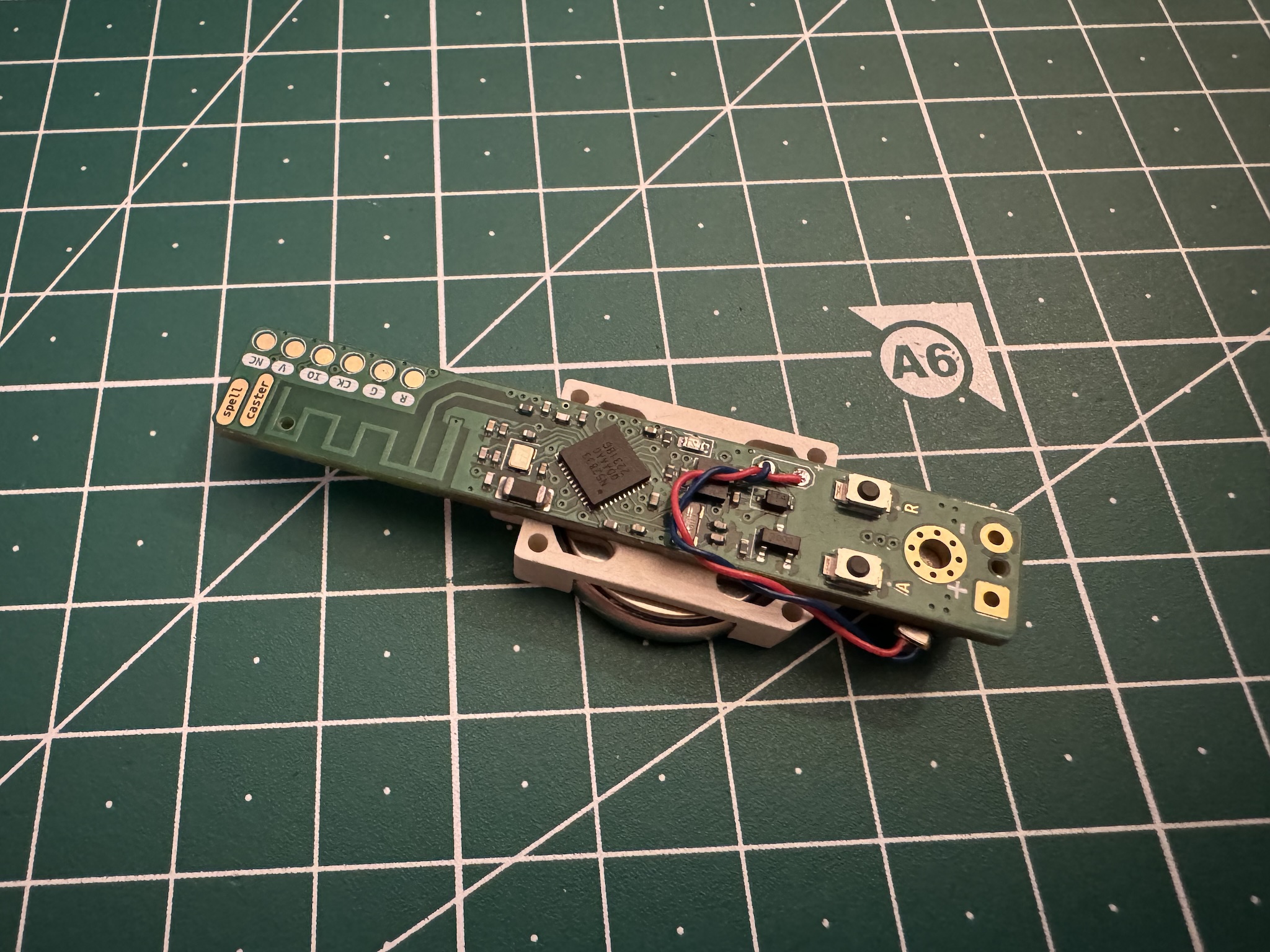
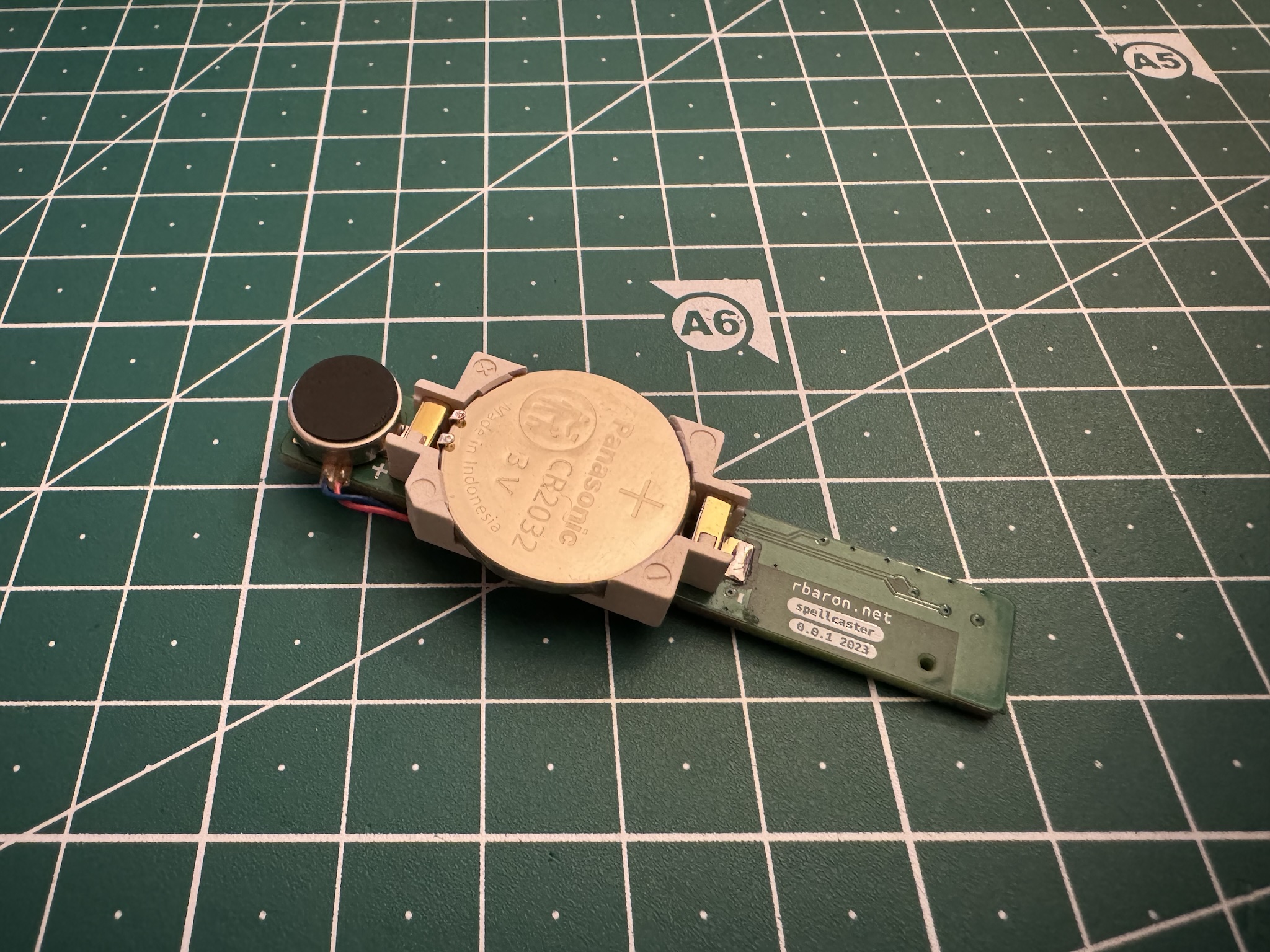
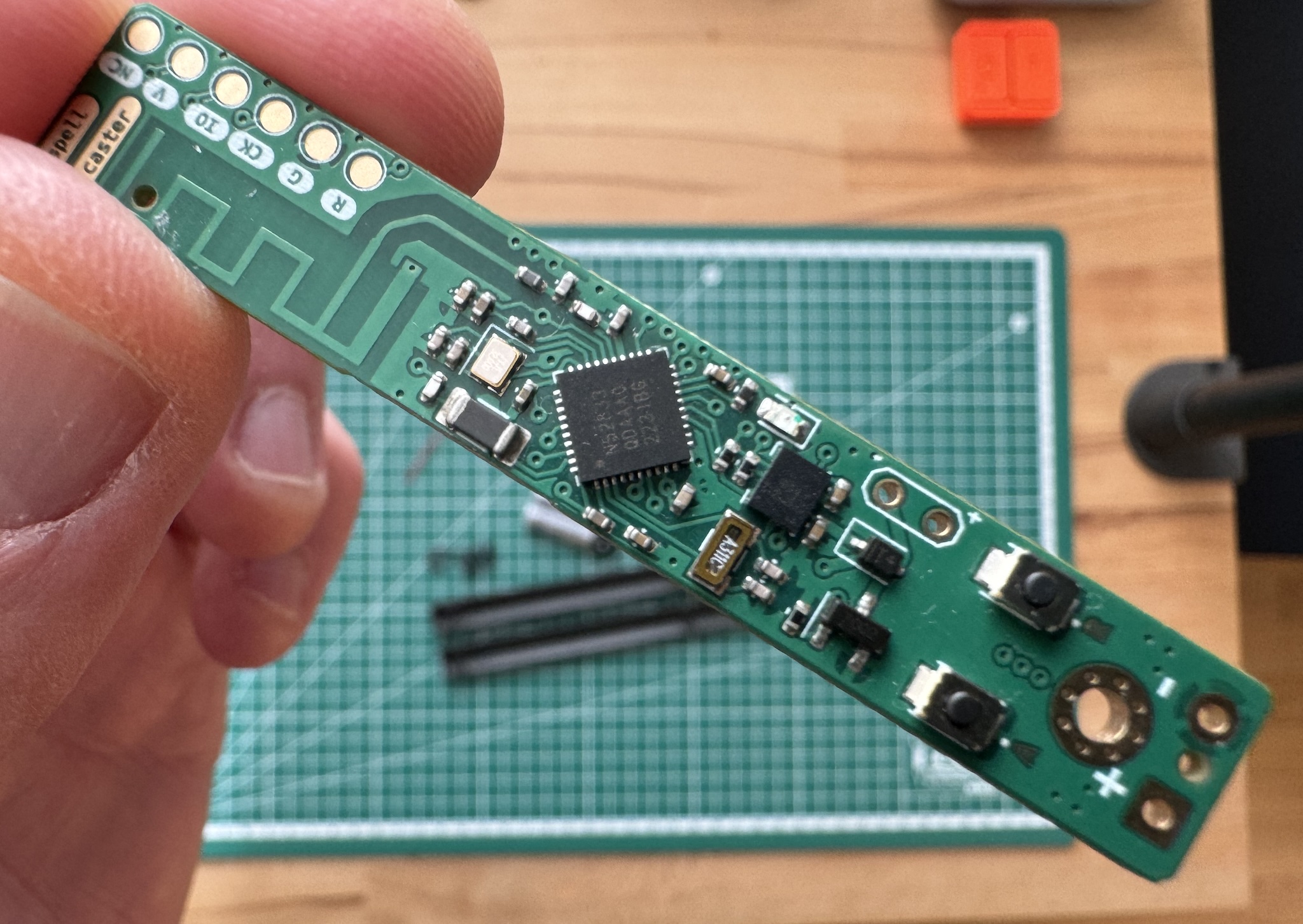 spellcaster’s printed circuit board (PCB)
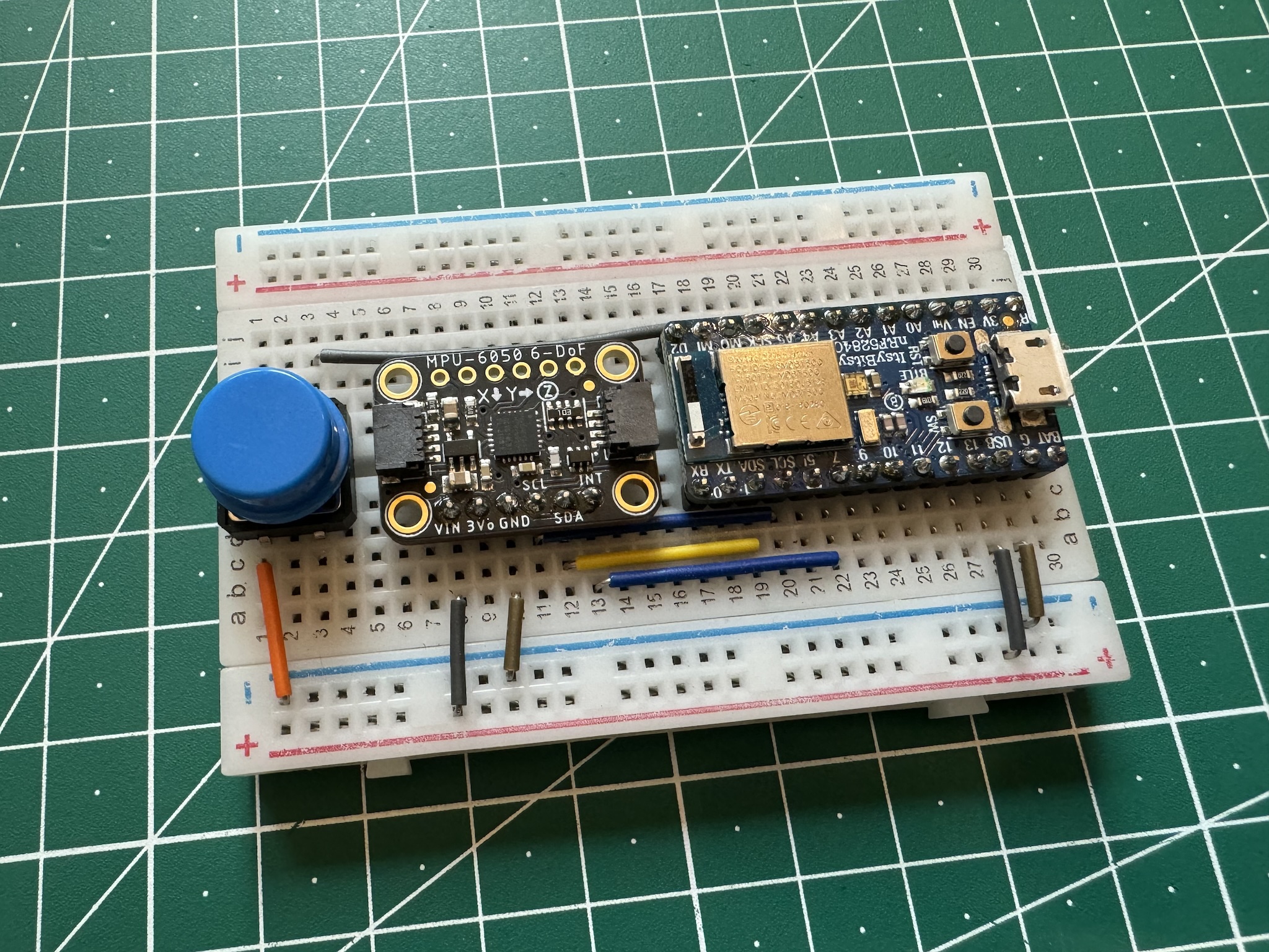
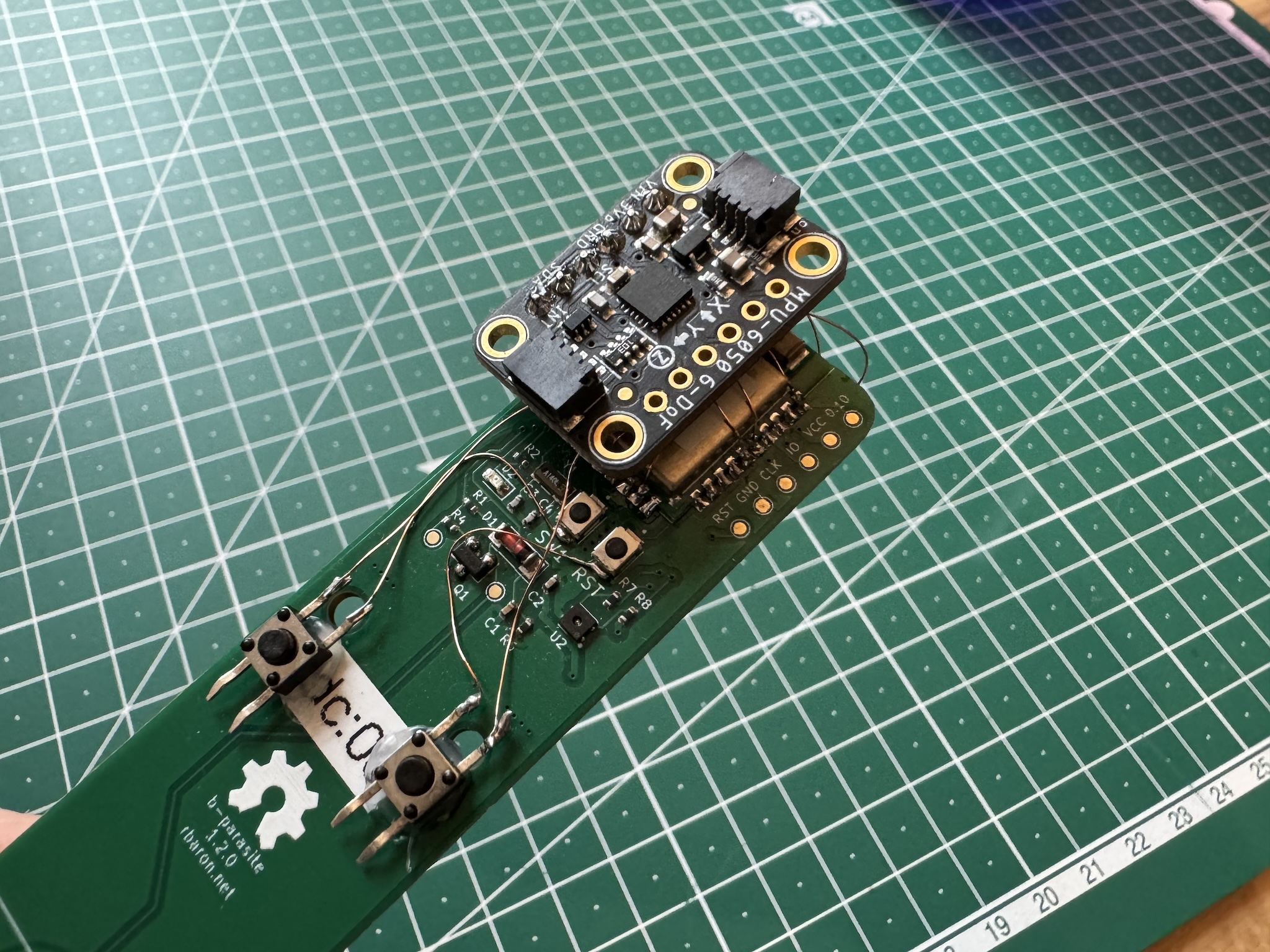
The idea is to put together a device that is able to capture hand movements and trigger actions – like turning on the coffee machine, or switching the office lights on – when a gesture is recognized.
After proving the concept on two different prototypes, I designed the circuit board above, aiming for compactness and low power. I decided on a narrow, 10 mm wide board, powered by an nRF52833.
I went with the low cost, power efficient LSM6DSL IMU to capture gestures. Beside its six accelerometer and gyroscope axes, it has some useful built-in features for generating interrupts whenever it detects movement or it is still for some time. Hooking into those is a convenient for setting the main chip to sleep and save battery.
I thought, as I designed the electronics, that it would be nice if the finished wand had some mystery, some curiosity-sparking aspect to it – no visible buttons, LEDs, charging ports, no on-off switch. Something that would intrigue my friends when they saw it. To provide some discreet feedback during operation, I added a driver for these tiny coin-type vibration motors.
Optional Detour: RF Circuit Design
I have a few simple PCB designs under my belt, but mostly with an off-the-shelf module like this one. These daughter boards simplify the design considerably: the tricky RF (radio frequency) circuit and antenna network are done for us, and they come FCC and CE certified.
Due to the high frequencies in the RF path – 2.4 GHz for Bluetooth, ZigBee, WiFi – many things outside of my usual, already spotty electronics mental model become critical. I have always had a careful curiosity and respect for that territory, but ultimately thought of it as a job better left to the experts.
This time, on such a narrow board, I could not fit a pre-built module. It seemed like the perfect excuse I needed to learn the bare minimum of RF design and try my luck at it. I collected a bunch of resources on the topic and got to work. These were my favorites:
- Phil’s Lab on YouTube. Phil is not only incredibly knowledgeable, but also a great teacher. Both the ESP32 + PCB Antenna Hardware Design Tutorial and KiCad Controlled Impedance Traces were invaluable. These two videos and his encouragement made it seem possible that I could diligently follow the best practices and arrive at something that works, even if not optimally, without breaking the bank on tuning equipment
- Michael Ossman: Simple RF Circuit Design
- Andreas Spiess’ Inverted-F PCB Antenna: How to tune PCB circuits using a NanoVNA
- Silicon Labs: Designing an Inverted-F 2.4 GHz PCB Antenna
- Texas Instrument: Small Size 2.4 GHz PCB Antenna
It was all very well out of my depth, but it turned out as the most rewarding part of the project for me. These beginner’s rules of thumb guided me through it:
- Use Nordic’s reference circuitry with base component values for impedance matching
- Use your fab house’s controlled impedance calculator. It will give you a trace width for your RF section based on the PCB material, number of layers, and type of network and goal impedance – almost always 50 Ohms
- Choose a battle-tested, well documented antenna design. I went with a PCB antenna, which means the antenna itself is made out of copper traces on the PCB. KiCad already has a footprint for the one I chose. Make sure to follow the designer’s recommendations about connections, vias and copper planes under the antenna
Surprisingly, out of fear, hope and good intentions, out came a PCB that gives me comparable wireless range to the modules I have been using. It’s enough to cover my living area, so I will call it a mild success. Either way, I have been bitten by the radio frequency bug and I am already eyeballing a NanoVNA to actually measure and tune the circuit, which I am sure is far from optimal.
Spells
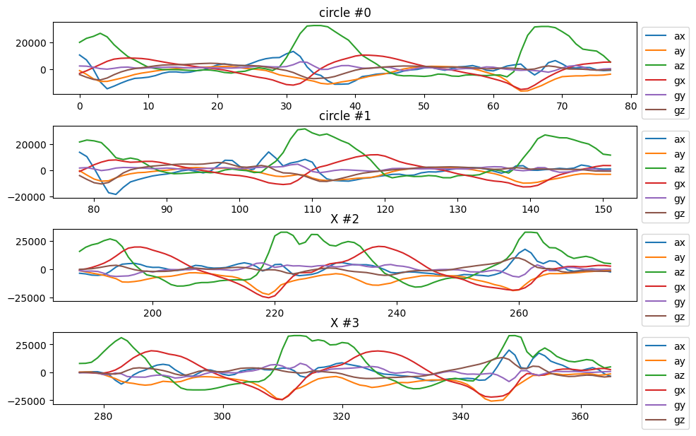 Example with four captured signals from the accelerometer and gyroscope
I want to capture and store different gestures with the wand’s accelerometer and gyroscope. Later, when I want to trigger an action, I perform the corresponding gesture and match it against the stored ones.
I plotted the raw IMU readings for two different gestures in the figure above: the first two rows are me doing a vertical circle with the wand; the last two are me doing a vertical “X”. See if you can recognize these two gestures in the “spell recording” video at the end of the post. Notice how similar the raw signals are across the two gestures, and at the same time how different they are for the same gesture.
Good. Now we’re in the market for a way to compare a pair of such signals. The comparison should ideally be forgiving of small differences in the signals. For example, if we linger a little longer on the top part of a circle, or we do a shorter “X”, we still want to match.
Dynamic time warping is a popular algorithm for such classes of pattern matching problems. It finds the optimal “stretching” of a pair of signals such that the alignment between them is optimal. In the example above, even if we linger on the top part of a circle for a little longer than the stored signal, DTW will warp the signals so the match is still good.
The output of this warping process is a mapping between the time points of the two signals. For us, this is a mapping between indices of two arrays of IMU readings.
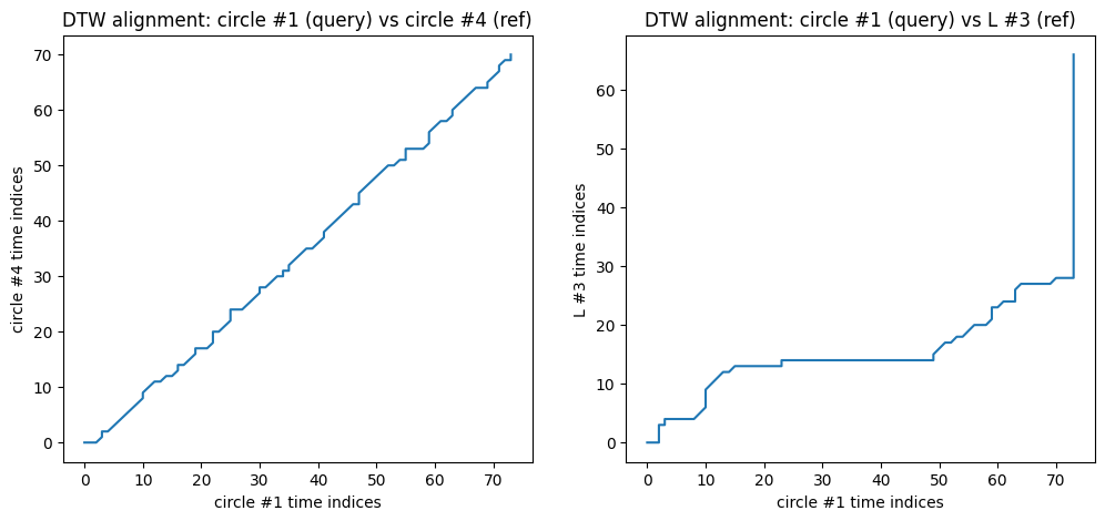 DTW alignment between two pairs of signals
On the left, the line near the diagonal means that not a lot of stretching was needed to align the pair of signals – each point in one signal corresponded more or less to a similar point in the other. We may conclude these two signals are instances of the same gesture. They are, indeed, the same gesture – two different instances of doing a vertical “circle” with the wand.
On the right, the result of optimally aligning two distinctively different gestures with DTW – a circle and a vertical “L”. The alignment is not good, as it should not be.
We can then take this distance from the main diagonal, normalized to account for different signal lengths, as a measure of the similarity between two signals. A small distance – line is closer to the main diagonal – means the signals are similar, and a large distance means they are different.
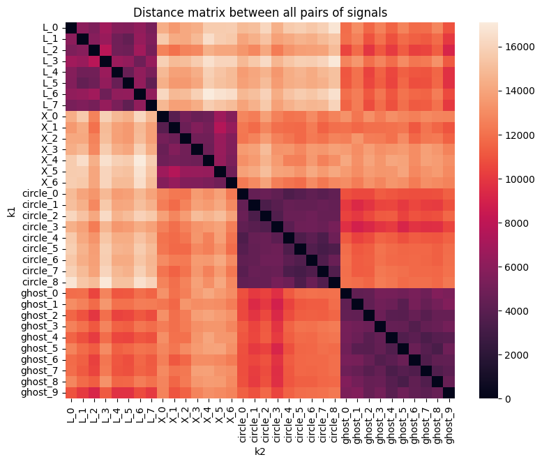 Distance matrix for pairs of signals
The above figure plots the distance between many pairs of signals. There are 4 different gestures, each executed a few times. The purple squares represent islands of similar signals, as their distances are small.
We can visualize the same distribution of pairwise distances above in a different way:
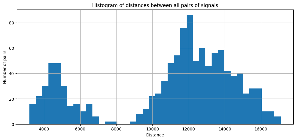 Histogram of pairwise signal distances
The bimodal distribution of distances is great news. The first mode to the left are distances between signals that represent the same gesture. The one to the right, between different gestures. I then used a visual deep neural network to find the optimal threshold between the two groups (I eyeballed a vertical line between them): if the normalized distance between a pair of signals is smaller than 8000 or so, I consider they correspond to the same gesture.
While it is possible to define two different gestures that are very similar – for example, a circle and an ellipsis, or an “X” and a “Y” – the assumption here is that gestures are sufficiently different, so don’t do that.
Rotation Invariance
I tried to preserve the radial symmetry of the wand as much as possible. I wanted to be able to pick it up and perform a gesture without having to first rotate it alongside the main axis to match the same frame of reference of the stored gesture.
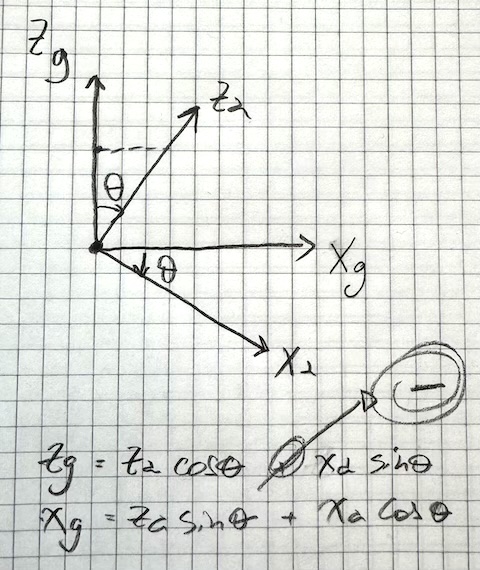 Original manuscript: 2D frame of reference rotation between accelerometer (
a) and Earth (g) references
To achieve this, in the beginning of a movement, as the wand is horizontal and still – this works as the trigger for an incoming gesture anyway – I read the accelerometer. Since it’s not moving, the only acceleration it experiences is gravity, and I can use it to estimate the orientation of the wand. The signals are then projected from the spellcaster’s frame of reference to the Earth’s frame of reference in this fashion. We can then properly compare any two signals regardless of their initial orientation.
There’s RAM for Improvement
The naive DTW algorithm is a beautiful, concise instance of dynamic programming, but it’s quadratic in space and time on the lengths of the inputs. It’s fast enough for a gesture of a few seconds and a slow sample rate, but it very quickly hogs all the available CPU and RAM.
The FastDTW paper introduces a linear approximate algorithm, but apparently there is some debate on the real-world speedups it provides. In practice, common approaches exist to artificially constrain the search space of the naive DTW algorithm. Some of them constrain the search space to some band around around the main diagonal:
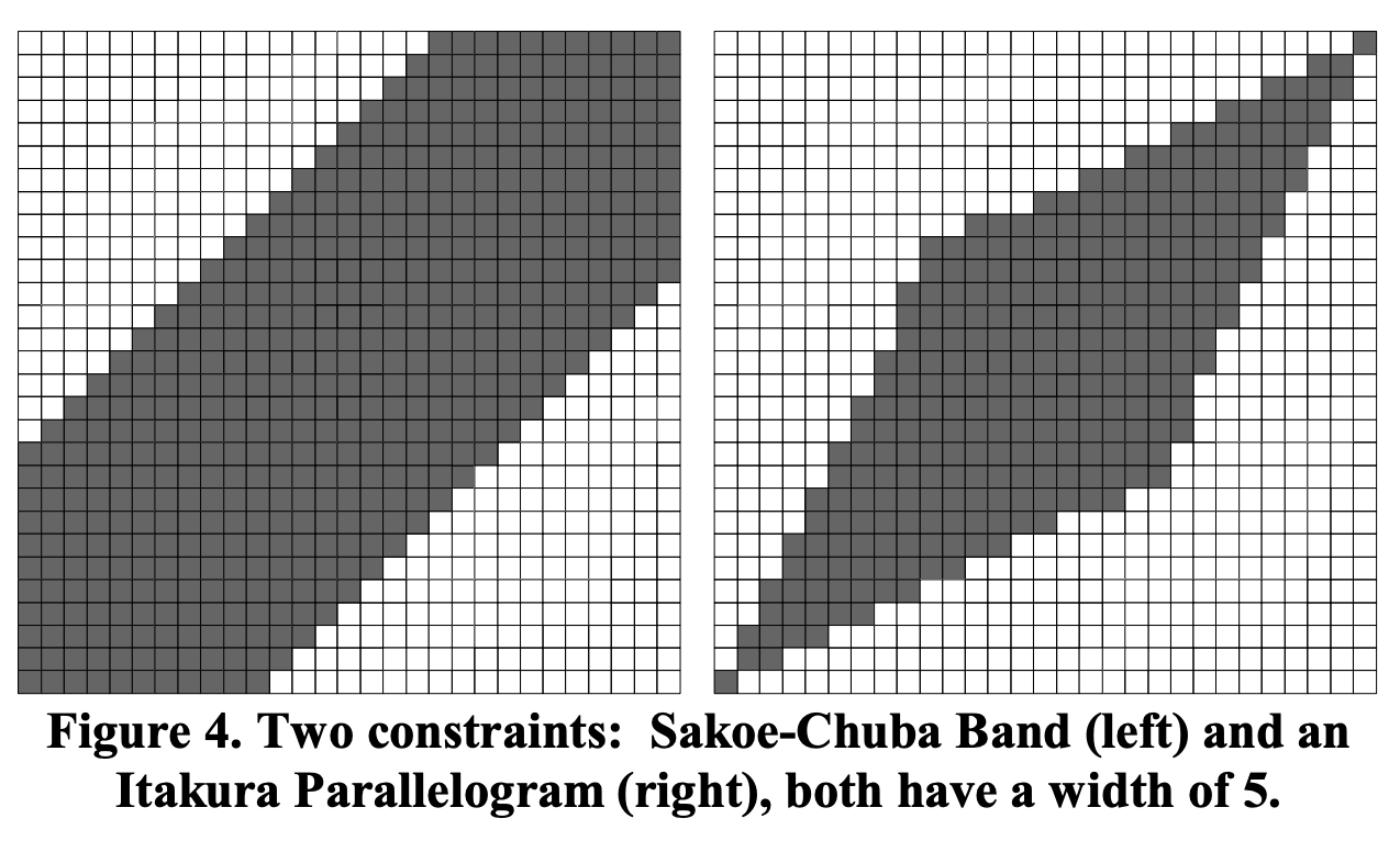 Example of DTW bands – the search space is constrained to an area around the main diagonal. Figure borrowed from the FastDTW paper
I implemented both the naive DTW and the Sakoe-Chuba band version. With the band, the distance matrix still takes 30% of all the RAM, even when capping the maximum spell length to 3 seconds at 52 Hz. It’s not for free though – using the artificial constraint theoretically means there will be more misfirings, as we don’t let bad matches stray so far from the main diagonal.
Most of the time, though, we do want something to happen. Even if a wrong gesture’s match beats the threshold, the correct gesture will be an even better match and we will pick that one. In that sense, the windowing approach is okay, and in practice I pretty much always get it to do what I want. The misfires are more annoying when we do not want stuff to happen, like when putting away the wand or not paying attention.
I hacked some workarounds for those accidental triggers. For example, both the start and end states of a spell are the horizontal, still position. This adds some intention to the gesture, makes misfirings less likely and it’s in general a good anchor point for the apprentice wizard. You can see this behavior in the demo at the beginning of the post.
I manually tried a few band widths and found that a window of 20 time steps is an okay compromise between speed, space and accuracy. Optimizing the window size is a good candidate for future work.
Power Supply
While we could get away with a tiny CR2032 battery (at least for fun), it’s too wide. I did, in fact, choose the 10 mm PCB width based on the diameter of an AAA battery. The much higher capacity of a pair of AAA cells (1000 mAh, over 200 mAh for a coin cell) is a good bonus problem to have. I can power all the components directly too, without losses in external voltage regulator.
Low Power Mode
One of the reasons I really like the nRF52 chips and its Zephyr-based nRF Connect SDK is how centered around ultra low power they are. Whereas in the past I spent many hours fighting both hardware and software platforms to reach a nominal low power state, Nordic really makes it easy to get there. As long as you disable unused peripherals, a sleep() call is all you need to get down to ~1.6 uA @ 3 V. It’s fantastic.
The accelerometer theoretically adds up 3 uA while in power down mode. I do, however, use the “wake up interrupt on movement” feature, which means the accelerometer is always on, albeit in a low power mode. In this low power, movement-aware state, the average idle consumption is around 65 uA:
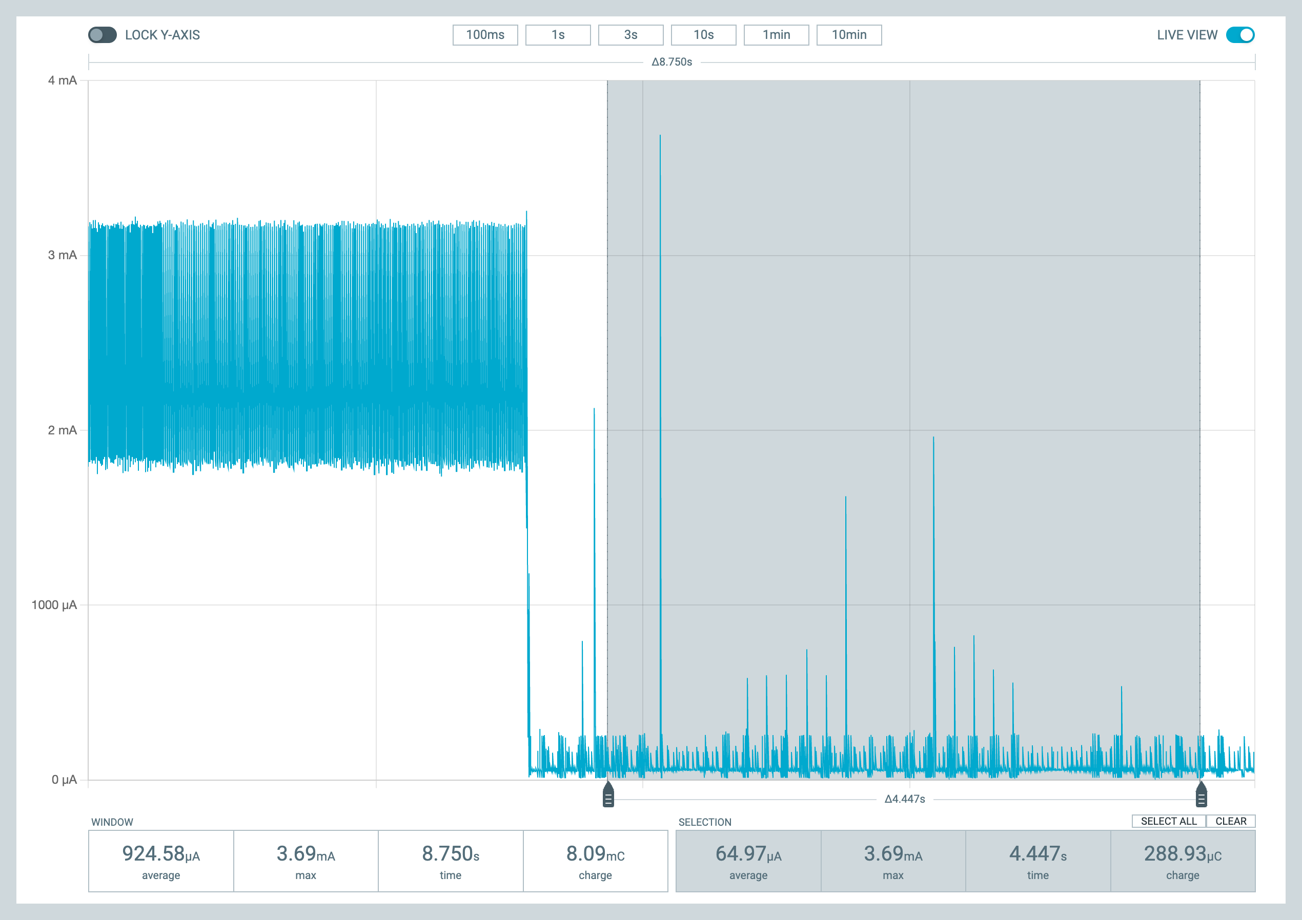 Average current consumption in idle mode
In active mode, the current is about 2.4 mA. In normal use this mode is only active for a few seconds at a time. Even without much optimization, the battery should last for around one and a half years. Not perfect, but good enough for a first approach.
We can do better, though. There’s little need for super fast reaction times. If we manage to get out of idle mode in the generous half a second it takes to pick the wand up and get ready for casting a spell, it’s all it’s really needed. I would bet we can turn the whole thing off and just check for movement once every 100-200 ms. Depending how fast we can perform that check, I expect to cut down the idle power usage to 1/4 or less, bumping the battery life to a few years. Something for the future.
Case
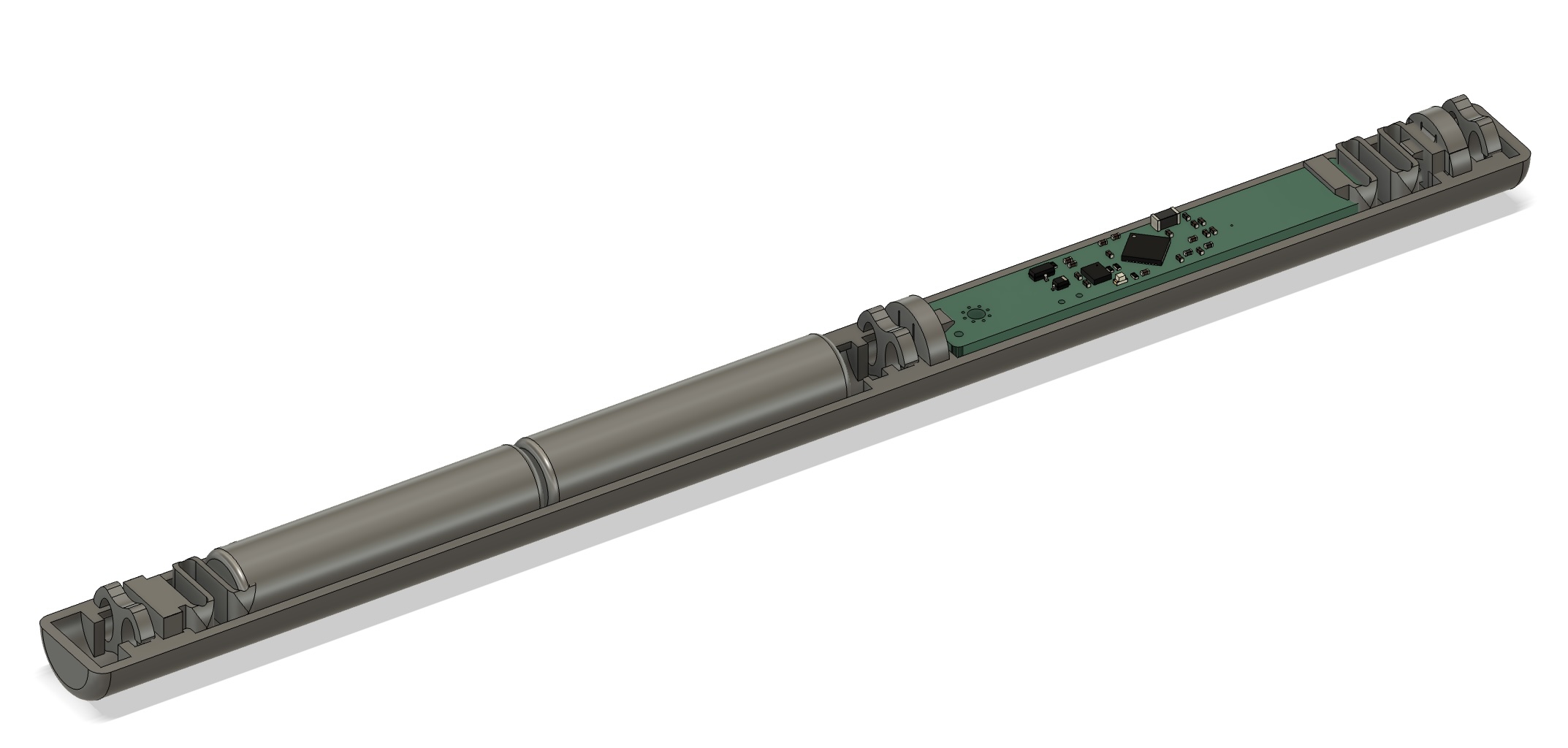 Case in Fusion 360
The idea to keep the wand’s look and feel intriguing, magical, as deceptively simple as possible was always in the background. It would ideally feel just like an inconspicuous, underpromising, seamless rod that somehow did things when held it in a certain way.
My first thought was to print a hollow cylinder vertically, slide all the components in from the bottom and close it with a cap. My inaptly maintained, four-year-old, entry level printer disagreed.
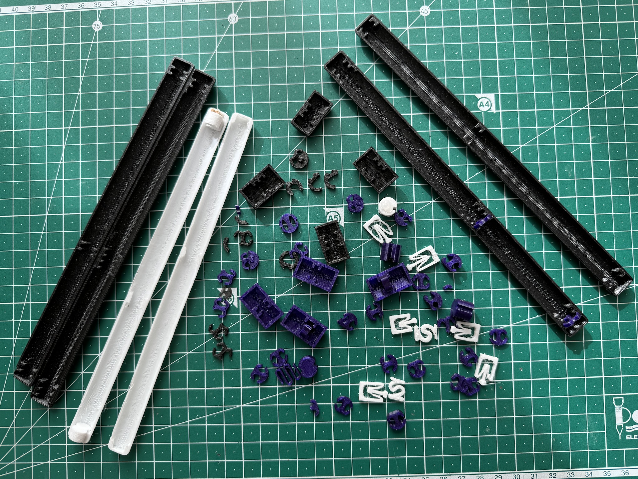
A few lessons later, I arrived at a clip design that allows me to print each half separately, and (mostly, sometimes) satisfyingly snaps shut. I initially used a metal spring to hold the batteries in place, but I later designed a 3D printed spring too.
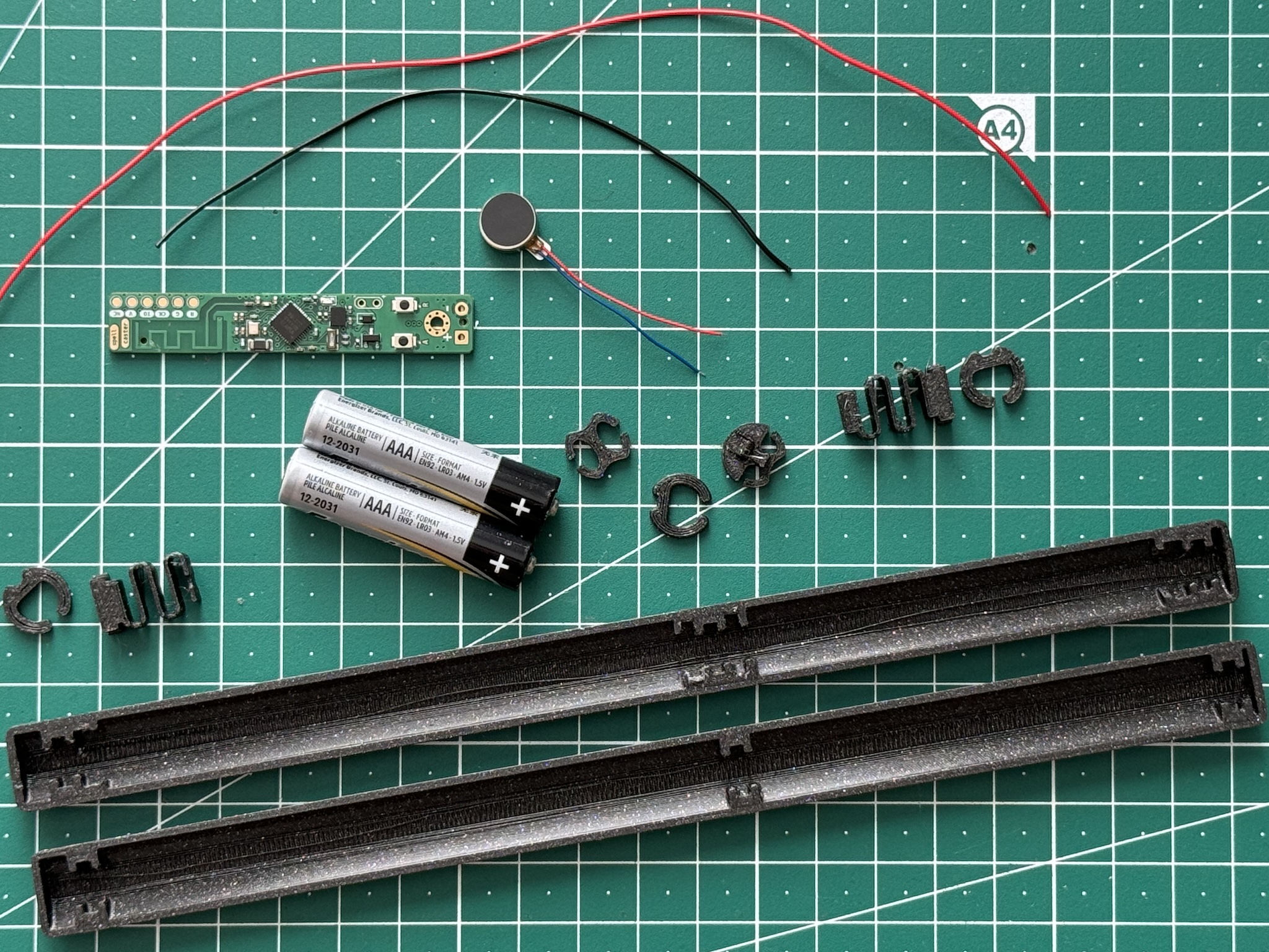 All parts ready for assembly
Assembly
If you are in the mood for seven minutes of ASMR, here’s a video of me assembling the wand from start to finish:
Programming
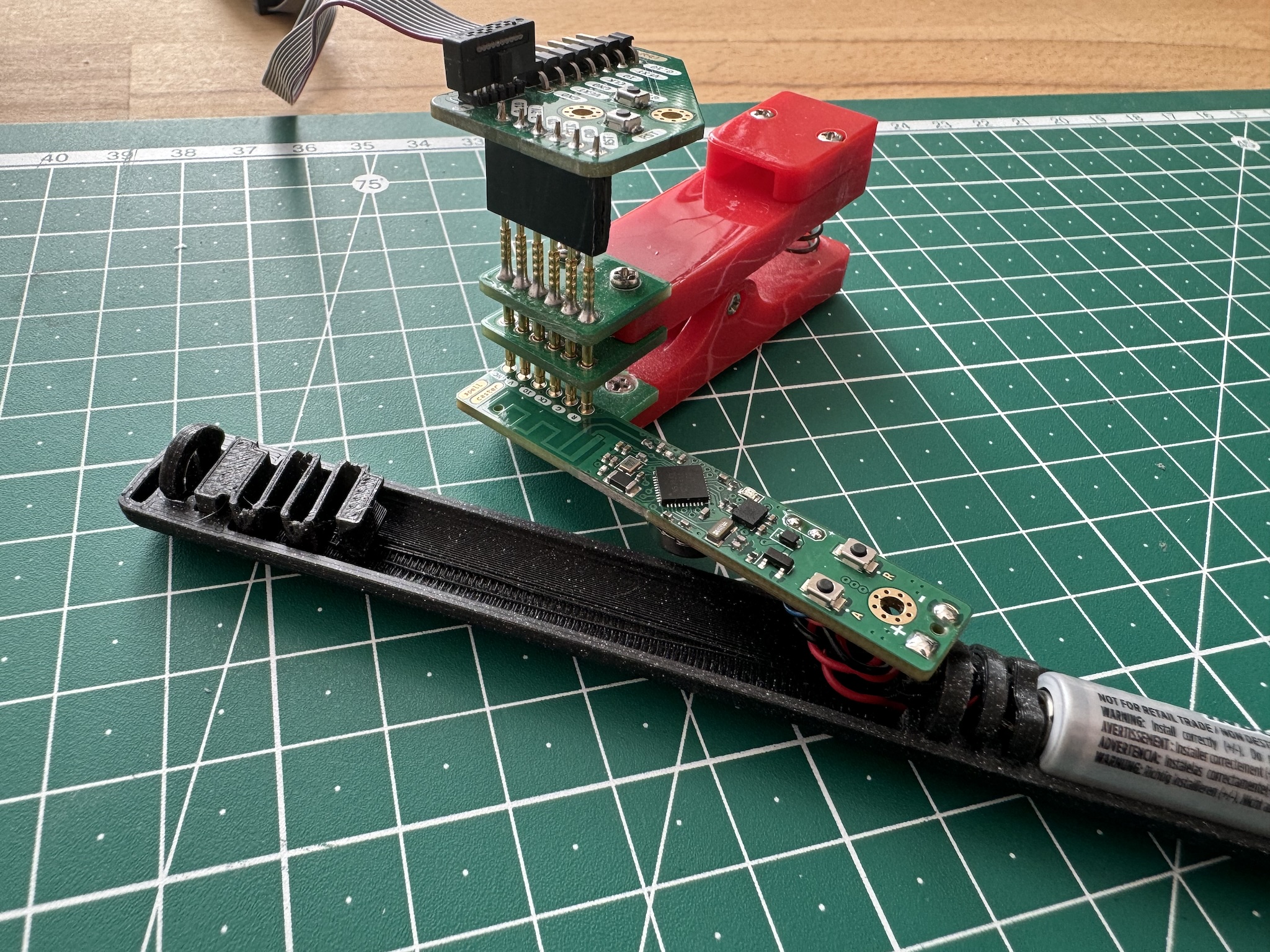 spellcaster and programming jig
The programming interface is just the main chip’s SWD pins exposed as test pads. I have used this approach in all my recent projects, so I can just reuse the same programming jig. It’s really simple: no extra components, no additional connector height, no extra cost. The pogo pin clip is not as stable as a proper JTAG connector, but I really like it for these types of low profile projects.
Hooked to the pogo pin clamp is a J-Link EDU Mini, which I use for flashing, logging and debugging straight from Visual Studio Code with nRF Connect for VS Code. It’s great.
Networking
At this point we have a way of recording and matching spells. The last piece of the puzzle is to actually issue an action when a spell is cast.
BTHome
The simplest useful action is issuing a bthome.io button press. These are standardized Bluetooth Low Energy advertising packets that Home Assistant understands. I mapped spell #1 to “single button press”, spell #2 to “double button press”, and so on.
This way, everything works out of the box and you can trigger any automation you’d like inside Home Assistant:
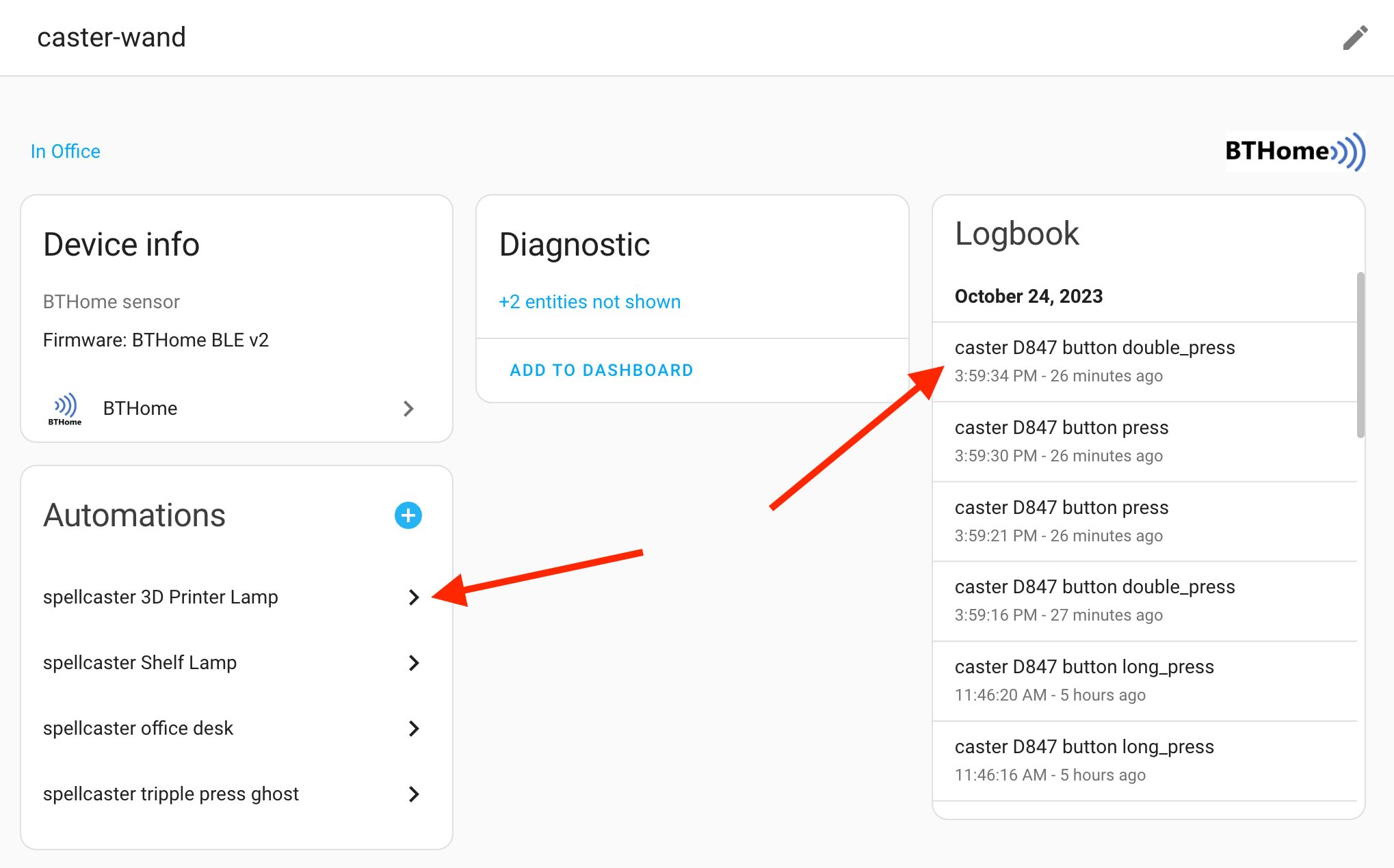 Home Assistant & BTHome integration
Zigbee
nRF Connect SDK ships with the ZBOSS Zigbee stack. It’s a quirky API to learn, but I managed to adapt one sample and get it to work with spellcaster. As a nice bonus, we can monitor the wand’s battery, RSSI signal strength, connection to other Zigbee routers out of the box.
It’s also two-way communication, so we can for example trigger a motor vibration on the spellcaster via a Home Assistant button using the standard Zigbee identify cluster, or even remotely update the firmware, although I haven’t explored that yet.
On the Home Assistant side, I use the Zigbee Home Automation (ZHA) integration. To teach it about spellcaster and its capabilities, I had to write what is called a ZHA quirk. This piece of code identifies spellcasters by their Basic Cluster attributes (such as model name, manufacturer name). Once this quirk is installed, Home Assistant will know how to map spellcasters’ Zigbee cluster actions into different types of human-readable actions. At this point we can, like with BTHome, configure any automation to run when a spell is cast:
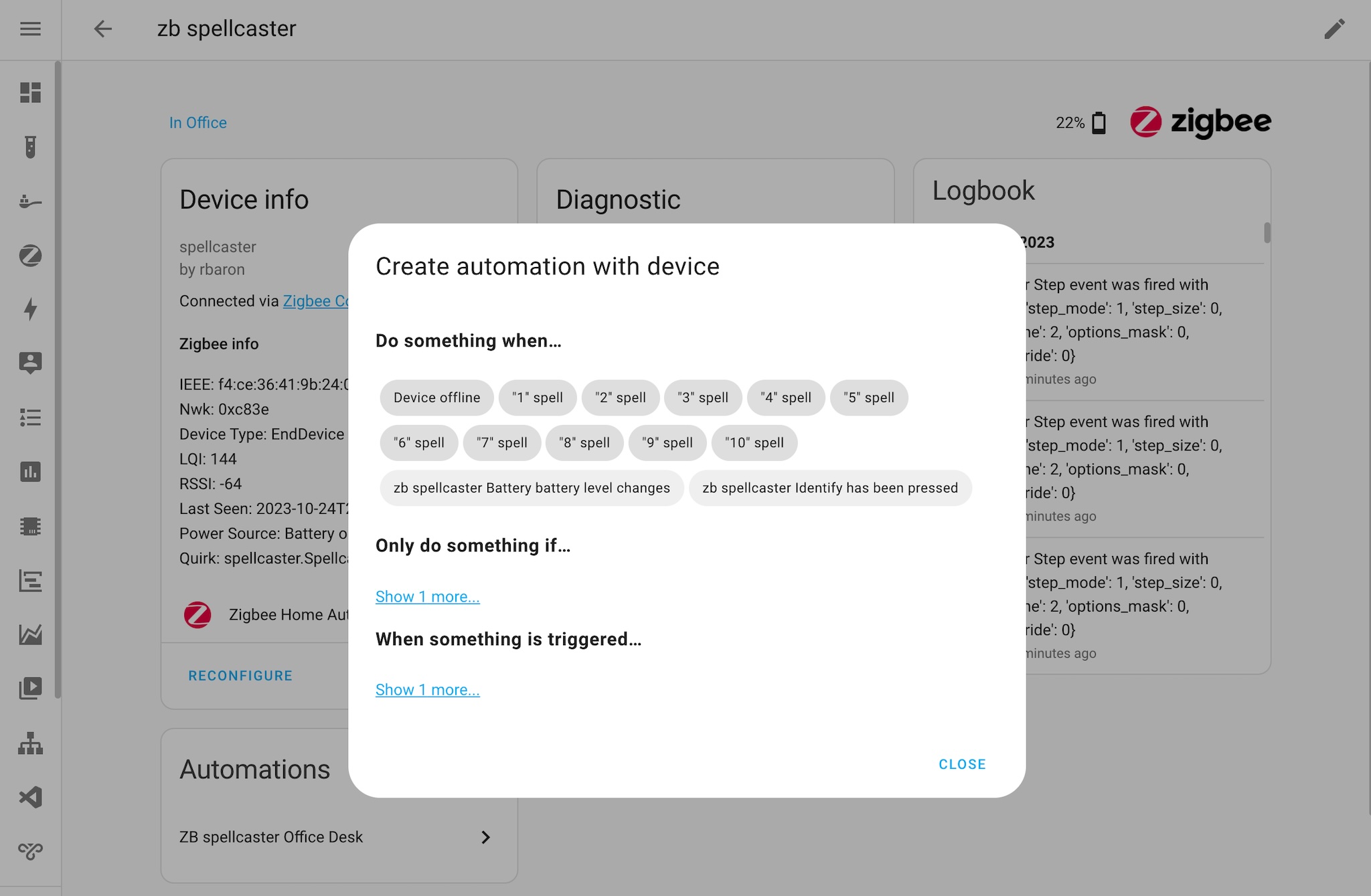 Zigbee spellcaster in Home Assistant
Believe it or not, the Zigbee Cluster Library spec does not even touch on the subject of magic wands (I checked). I had to freestyle the implementation a little bit: from ZHA’s perspective, each spell looks like a “brightness up/down step”, as if issued by a Zigbee light remote. To keep things even unholier, the step amount corresponds to the matched spell slot. Then, the ZHA quirk maps that action into a human-readable name for the UI, as seen in the screenshot above. It’s hacky, out of spec, but hey, it kinda works when it works.
HID over BLE
The Bluetooth Low Energy (LE) specs define a Human Interface Device (HID) profile. This is what wireless Bluetooth devices like mice and keyboards use. Nordic’s nRF SDK contains a HIDS keyboard sample, made to demonstrate how to implement a basic keyboard via BLE.
Instead of responding to key presses, I adapted the sample to respond to cast spells from spellcaster. We can connect the wand directly to a computer or smartphone and have it simulate key presses. There are some interesting avenues to pursue here, like media control, apps shortcuts.
Demo
Learning New Spells
To store a gesture, we set spellcaster to recording mode. Pressing the A button n times will store the next performed gesture into slot n. The LED will flash a few times to confirm the spell was persisted to flash.
Casting Spells
After each spell is recorded, it switches into replay mode, where it will spend most of its life. In this mode, performed gestures are matched against all stored ones. The match with lowest sufficient distance wins, and that spell is cast.
After 10 seconds of inactivity, the whole system goes into idle mode to save battery. Once it’s picked back up, the accelerometer detects movement and automatically puts it back into replay mode.